I’ve been reading about the Oskitone 555Poly which looks like a lot of fun. It is a fully polyphonic sound generator based on one 555 oscillator circuit per key, each one individually tuned to the note you want it to play. Unfortunately my budget for making is unlikely to be able to justify getting one myself, but the full development, build and design details are available on github here and it makes for fascinating reading.
This project is not attempting to “build my own” but I was inspired by the idea of an oscillator per key and so I thought I’d spectacularly miss the point of the Oskitone and attempt to use a microcontroller to give me a tunable oscillator output for as many keys as I could manage.
In the process, I’ve managed full 12-note polyphony (as long as you only need 12 notes in total) on an Arduino Uno. Here is how it works.
- In part 2 I add the ability to “scan” a matrix of keys.
- In part 3 I expand it to four octaves.
- In part 4 I build an output shield.
- In part 5 I tweak the timings to get better tuning.
- If you still want more, you can follow this up with my experiments with an Arduino Top Octave Generator.
Warning! I strongly recommend using old or second hand equipment for your experiments. I am not responsible for any damage to expensive instruments!
These are the key tutorials for the main concepts used in this project:
- Oskitone – How does it work?
- Arduino tone()
- How to build an Analog Mixer
- Brett Hagman’s Tone Library
- Arduino Port Manipulation
If you are new to Arduino, see the Getting Started pages.
Parts list
- Arduino Uno
- 12x 10k resistors
- Audio amplification
- Arduino MIDI Interfaces for MIDI receiving
- Breadboard and jumper wires
The Circuit
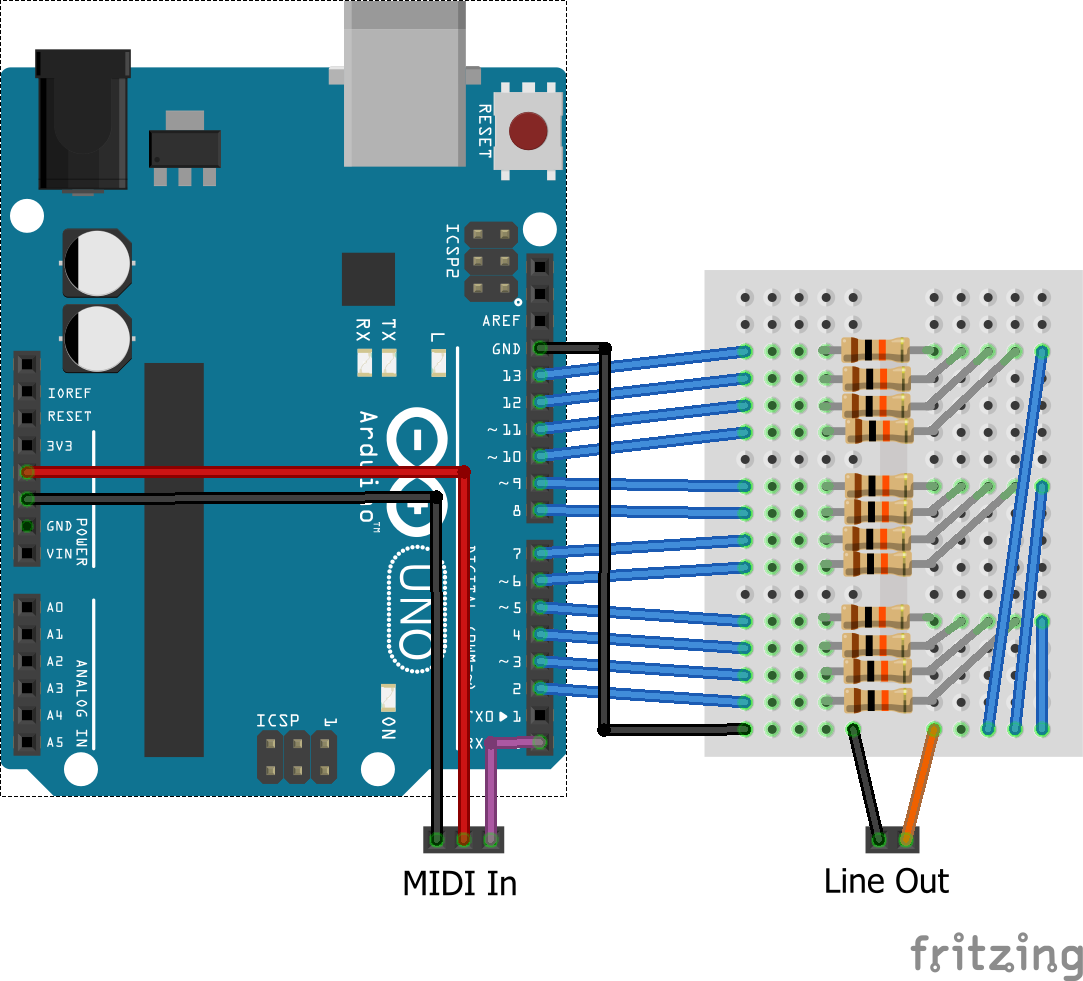
The circuit is effectively one large passive mixer combining all output pins into a single output which can (if you squint) be plugged into some amplification. There is no special electronics here so I have a very cavalier attitude to such things as impedance, peak voltage and similar concepts, so my usual warning is particularly relevant here. To be clear:
Do not use this with expensive equipment or anything that you aren’t happy to sacrifice in the course of your experiments!
My quality assurance process is “hey, this works for me” and I provide no other assurances…
The outputs from each pin is a 0 to 5V square wave. By the time that goes through 10k resistors into some kind of load that is a much smaller voltage. Attempting to drive a speaker directly was a non-starter it was too quiet, but it seems to work well with something expecting a line-level input. It is still a biased signal at this point though – one simple enhancement would be to take it through a coupling capacitor.
In theory with 12 outputs the worse case will be the 12 times the peak voltage of the voltage divided single output. In reality we tend to get an averaging effect so it is mostly much less, but not being an electronics person I haven’t done the maths for this one.
We also have to be mindful of the current draw of 12 pins all HIGH the same time. Again I haven’t done the calculations, but I’m using a 10k resistor on each pin, so it should be largely ok… probably… errr.
A MIDI in circuit is connected to 5V, GND and RX – in the video I’m using my USBMIDI to MIDI Shield.
The Code
The Arduino tone() functionality is provided by using one of the Arduino’s timers to output a square wave with a specific frequency directly onto one of the IO pins. The timer fires off with a specific period which is determined by the frequency used with the tone() call. The standard built-in tone() library function can support a tone on any IO pin as it simply toggles the output between HIGH and LOW at the required frequency. But it can only do that for one pin at a time.
There is an upgraded library which I talked about here: Arduino MIDI Multi-Tone Module. This will allow as many simultaneous tones as your board has timers. For the ATmega328 based boards, such as the Uno or Nano, that means three timers so three tones. If you have an ATmega2560 or ATmega1280 then you have six timers, so can produce six tones.
This is all because each timer has its own interrupt routine, firing off at a specific frequency, tied to an IO pin. On the face of it that would appear to be the limit of tone producing without getting into digital synthesis (which I talk about elsewhere on this blog of course).
So I started to wonder if it was possible to have a single interrupt routine, driven from a single timer, servicing several pins at once.
The answer, if you just want to try it – is yes! I can have a single interrupt routine from one timer TICKing at 40uS servicing 12 different pins and have each pin tied to a specific frequency corresponding to the notes C3 to B3 which are played by receiving MIDI note on and off messages.
You can see the result in the video above. The Arduino really is playing 12 tone() type notes at once!
There are a number of nuances as to how this can be achieved, which I go into below, but the key elements for this initial explanation are as follows:
- I am using a “custom” initialisation of the Arduino MIDI library in order to allow each MIDI.read() call to handle all messages it receives in one go. Without this it just processes single bytes at a time, and needs to wait for the next call to handle the next message which takes time.
- There are two main threads of execution – the TICK which worries about which pins to make HIGH or LOW and when; and the normal loop() which only has to service the MIDI messages.
- I am using Arduino direct PORT IO to send values to the IO pins. If I was to use digitalWrite individually for each pin it would take far too long in the interrupt routine and there would be no chance of it working fast enough.
- I initially tried a 20uS TICK but running at this speed for 12 notes meant that I was starving the loop() of processor time, meaning I would miss MIDI messages. 20 uS was ok up to about 10 note polyphony, but I really wanted an octave! So 40 uS was used instead.
- Following the principle from the Oskitone, I’ve opted for each pin (so each “oscillator”) representing a single note. This may change in future experiments.
- I maintain a counter per pin, which is initialised with the number of counts for the frequency that pin is going to handle. The interrupt routine counts down for every pin on each TICK and when any of the counters reach zero the state of the pin is flipped (HIGH goes LOW or LOW goes HIGH), and the counter is reset to the value for the frequency corresponding to that pin.
- To keep processing as minimal as possible in the interrupt routine, I am using 16 bit values and bit masks to work out which pins need to be set or reset, and which notes are playing.
- This is translated into two 6-bit values for writing out to PORTD (bits 2 to 7) or PORTB (bits 0 to 5) to drive the IO directly.
- I included a test mode which simply toggles A0 as a digital IO at the start and end of the interrupt routine. You can see what percentage of time is spent running in the interrupt routine by seeing the width of the pulse on the oscilloscope in the video. You can see that for 12 notes at 40uS it is about half of the processing time.
I think that is about the lot. There are comments in the code with more details.
Advanced Discussion
The basic idea of sharing a TICK routine across pins would be simple for a tone and a tone at an octave above or below it. As one is twice the frequency of the other, just toggling the output pin every other interrupt TICK would do the trick. But what about if there are more complex frequencies involved? Well if we can work out how many TICKs make up each frequency, then in theory we could maintain a counter for each note and count the TICKs until the pin for that note needs to toggle state.
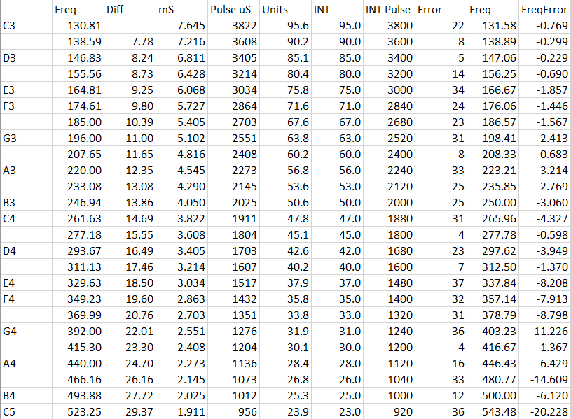
The frequencies for the notes C3 to C4 range between 130.81 and 261.63Hz. There is a formula to calculate the notes in between, which involve the 12th root of 2, but we don’t need to worry about that here as there are many tables of frequencies out there. So my thinking was as follows:
- I turn frequency (Hz) into period (uS).
- I see if there is a common denominator (rounded) period that looks like it would, with some approximation, allow most of the frequencies to be reproduced.
- I work out the frequency that would respond to that calculated period.
- Then see how far away from the true frequency it is.
- It try different TICK values until I get something that gives me a low-enough-looking error across the range of notes I’m interested in.
The smaller the period is (in uS) the more accurate the frequency can be reproduced – but there is a trade-off here. I am going to have to be performing calculations for every pin while in the interrupt routine which will take some time to perform. If the time to do the calculations is greater than the TICK of the timer, then it won’t be able to keep up. In fact, if the time is less, but doesn’t leave much room for other processing then the end effect will still be not being able to keep up. So there is a limit on how small the TICK period can be.
In order to find it I resorted to “programming by spreadsheet” and created the following table showing the required frequency, the equivalent period in uS, and then the rounded and calculated frequencies for a specific TICK (in this case the 40 at the top – for 40uS) and their errors.
Here is a graph of the above required vs calculated frequencies – you can see they are pretty good for the lower values.
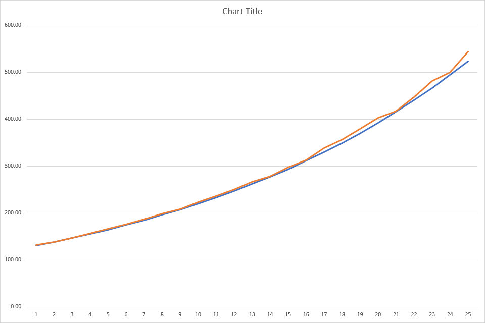
From the table you can see that the error in uS or Hz is pretty small for the lower notes (C3 to C4) but increases for the higher notes (C4 to C5). Having a TICK of 20uS yields much more accurate results but unfortunately was just too quick to allow much extra processing to happen – and I wanted to add MIDI handling too!
When I first tried it with my 20uS TICK I was missing MIDI messages, so I tried to optimise things a little more – by customizing the MIDI initialisation as described above; by making sure the RX/TX pins (bits 0 and 1 on PORTD) aren’t clobbered when I’m writing out to the rest of PORTD; etc. But in the end 20uS will only support 10 note polyphony – there is simply not enough CPU time to do anything else with more – so a 40uS TICK was the answer.
You can hear the results in the video. For that one octave, they aren’t too bad!
Closing Thoughts
This was largely a “what if” experiment inspired by the Oskitone. But as I say, it has really missed the point of the Oskitone, in that I’m using a microcontroller!
But I’m encouraged by the results so far on sharing a single timer, so will continue to experiment further. The next steps will be:
- Try different frequency ranges to see how bad the tuning gets as I go higher.
- Stack up several Arduino’s side by side to get a wider spread of notes for full “all note” polyphony.
- Create dynamic counter re-initialisation so that the frequencies aren’t fixed per pin. This would allow the module to recognise a much wider range of notes, but not with “full note polyphony” – it would only support as many oscillators as there are pins, but that could still be up to 12.
- Investigate the tradeoff between polyphony and note range. It may be that by restricting it to 8 note polyphony (say) I could maintain a more accurate frequency for higher notes and get my 20uS TICK back. With less note polyphony (e.g. 6), it might even be possible to go for a smaller TICK for even more accurate high frequencies.
But finally, now that I’ve found the technique can work, I’m intrigued to see what I can do with my Raspberry Pi Pico, which has 1 timer, a much faster processor, lots more IO pins, and hardware-optimised state-machines for IO that might take a lot of the load off the processor of toggling IO pins!
Kevin
