One thing that has been missing from all of my MIDI projects so far is some means of configuring the MIDI channel without having to reload code. There are a number of approaches, but I wanted one that used the minimal amount of IO. This documents one option.
- In part 2 I build this into a stripboard circuit.
Warning! I strongly recommend using old or second hand equipment for your experiments. I am not responsible for any damage to expensive instruments!
These are the key Arduino tutorials for the main concepts used in this project:
If you are new to Arduino, see the Getting Started pages.
Parts list
- Arduino Uno
- 4x SPDT “slider” switches (or similar)
- 1x 1k resistor
- Sequence of 4 resistors, each approx twice the value of the previous one (I used 1k, 2k1, 4k7, 8k2)
- Breadboard and jumper wires
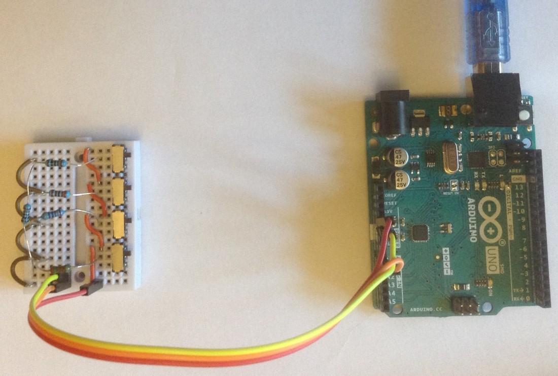
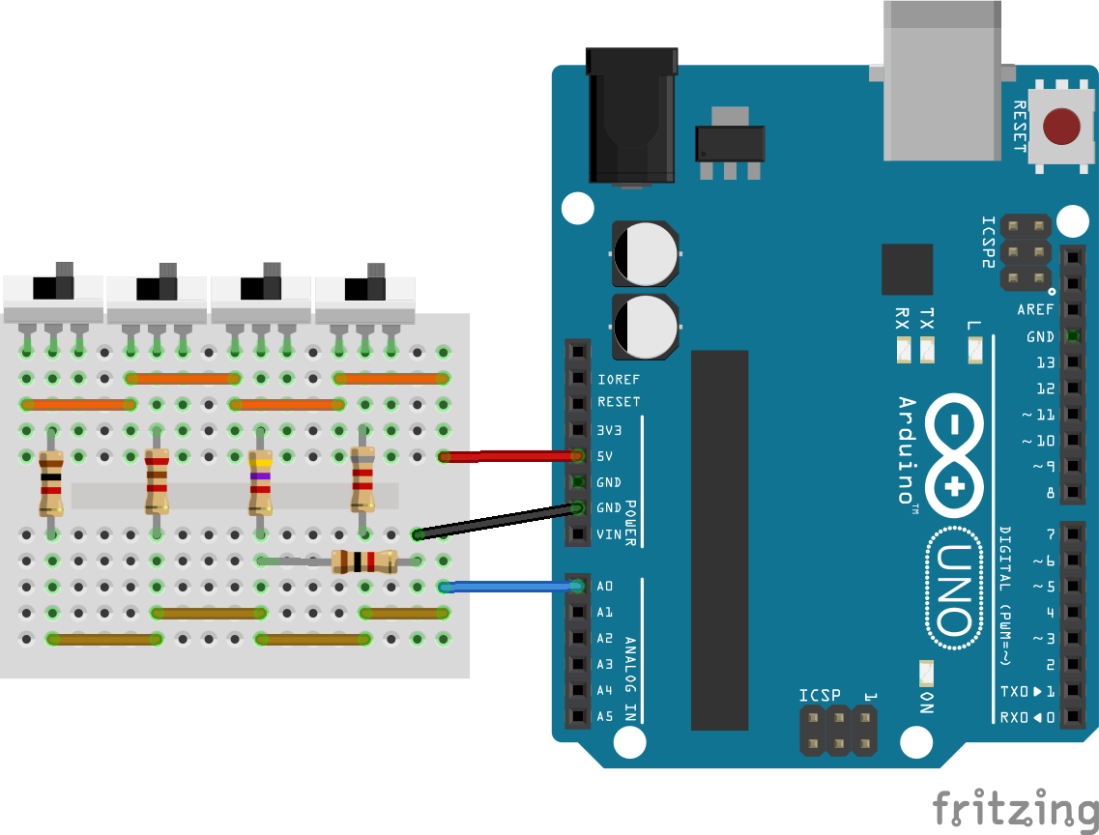
The Circuit
MIDI channels are numbered from 1 to 16, so any means that allows us to choose between one of 16 possible values would meet our needs. Some options I’ve thought about include:
- Having 16 switches linked up to digital IO pins allowing the correct one to be chosen. Simple, but uses lots of IO pins!
- Having a potentiometer on an analog input. Again simple, but not an accurate “user experience”.
- Having a rotary “multi-pole” switch linked up to digital IO. This is physically quite large and uses lots of IO.
- Using a “HEX” switch allowing you to choose the values 0-9, then A-F, again requires digital pins. This is probably the best “user experience” but these tend to be “BCD” coded (ask me another time) and uses a number of pins.
- Configuring the channel using up/down buttons. Simple, but needs some kind of user display to be useful.
- Sending the MIDI channel over the serial port from a computer (at start up before MIDI starts – “press a key to change the channel”, etc). Requires a computer.
- Sending the MIDI channel as a special MIDI message itself over MIDI. Requires booting in a “default channel” mode.
- Having a single switch to allow the choice between two values. Simple, but not very useful.
The one that I really wanted to implement was using a resistor network to provide a range of readable voltages on an analog pin. This has the advantage that it can be relatively exact from a “user-interface” point of view – switches are either on or off, unlike a potentiometer that provides a continuous change – yet can be implemented with just one IO pin, and provides natural user feedback – it is easy to see what channel is set.
The circuit is shown above. The basic idea is that each switch will “add” a resistor into a voltage divider, thus affecting the voltage read by the analog input. A complete description of the principles can be found here.
So how many switches and resistors are required? I take advantage of the fact that we need 1 of 16 values, and 16 values can be counted using 4 bits as follows:
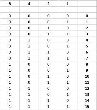
So four switches is enough to choose one of 16 values as long as we think in binary. The simple thing now of course would be to hook this up to four digital IO pins and then it is a simple matter of reading the four pins and calculating the MIDI channel according to the above table (adding 1 to convert from 0 to 15 over to 1 to 16).
But I’m after a one-pin solution, so back to that circuit, which looks like this as a circuit diagram.
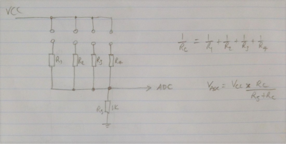
The voltage seen by the ADC is governed by the potential divider which consists of the R1-R4 combined resistance against R5. The combined resistance is calculated using the standard formula for parallel resistors, and the voltage is calculated using the standard formula for a voltage divider, both shown above.
As a general rule, we want R1-R4 to be unique, so that we can tell which switch is being pressed, but also to combine in useful ways so we can capture multiple presses. The hint about how to do this is to look back at the “multipliers” for the columns of binary numbers in the above table – 8,4,2,1. If the resistors are multiples of each other using these multipliers, then it should be possible to combine them in a useful way.
At this point I reached for a spreadsheet again to calculate the following: total resistance R1-R4; estimated voltage on the analog pin; estimated analogRead value given a range of 0 to 1023. I tried this for a range of values, then examined my resistor draw and finally settled on 1k, 2k1 (is is marked as 2k, but measures up as 2k1), 4k7, and 8k2. These are close to the 1,2,4,8 ratios, you’ll have to choose something suitable from what you have lying around yourself.
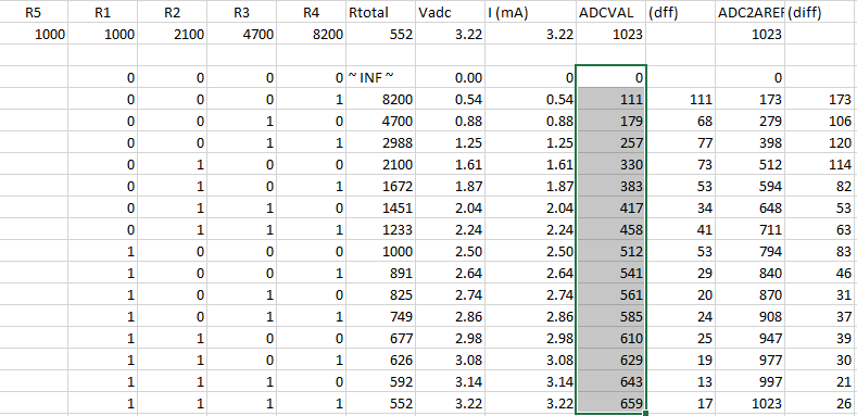
I’ve highlighted the theoretical analog values corresponding to each combination of switches, as these are the values I eventually used.
One thing I thought about was a neat trick from the “multiple switches” tutorial. As this is a potential divider it will never give us the full range of IO readings, as the voltage will always be less than the maximum potential supply voltage (the highest is 3.22V in the table above).
But the Arduino has an AREF pin which can be used to set the “analog reference voltage” for the analog inputs. If we set this to the highest voltage we could see from the potential divider then the Arduino will take this as the “1023” value thus allowing us to use the whole analog input range. I really liked this idea and it is the first time I’ve probably seen the AREF pin used properly.
But I decided I didn’t really need it in my case as it is extra components and needs a couple of extra lines of code (in every sketch using this idea), and it looks like I have enough variance in the values without it, so I left it out.
The Code
As already hinted at above, the trick is to chop up the analog input range (0 to 1023) into useful slots that correspond to the switches being pressed in any one of the 16 possible combinations.
In principle this can be achieved with a series of “IF value > low AND value < high THEN” type statements for each “slot” across the range. In practice this isn’t necessary, as I can just start at the top and look for values higher than the value I’m interested in. If I don’t find it, I simply drop down to the next one and do the same. If I get to the bottom, then we assume it is the lowest value (i.e. no switches active).
This can be seen in the following code.
#define ALG_ERR 8
int algValues[16] = {
   0,111,179,257, 330,383,417,458, 512,541,561,585, 610,629,643,659
};

uint8_t readChannel (void) {
  int val = analogRead (A0);
  for (int i=15; i>0; i--) {
    if (val > (algValues[i] - ALG_ERR)) {
      return i+1;
    }
  }
  return 1;
}
Analog input values are not accurate, they will vary from the theoretical calculated values due to two things (and possibly others):
- Temperature variations from the environment.
- Inaccuracies in the resistor values – all resistors have a tolerance, typically 5% or 10%.
For this reason, I’ve included an “error” value – ALG_ERR and accept a match if I read a value that is up to this amount below the theoretical value. This has to be small enough that it doesn’t overlap with the next lowest value, but big enough to capture any variation. Ideally perhaps it should be a percentage related to the tolerance of resistors used, but I went for a fixed value which seems to work for me.
Another good thing to do is actually measure your resistor’s exact values. I had one labelled as 2k but it reads much closer to 2.1k, which is still within a 5% tolerance. I used 2.1 in the calculation. You will get more accurate theoretical values if they are calculated with the measured resistances used. The downside of this is that your code becomes tailored to the four individual resistors actually in use for the one instance of the build.
In the code I count backwards from 15 down to 1, ignoring the “0” value in the loop, reading the values from the algValues[] list from highest to lowest. The code returns as soon as a match is found. If I don’t find a match I assume it is 0 and drop out to the bottom of the loop.
The index in the code is going 15 to 1, then 0, but of course MIDI channels are 1 to 16, so we need to add one to the index to get the resulting channel.
The actual code linked below prints values out to the serial port which is useful for examining the exact values read from the potentiometer. This too can be used to calibrate the values in the table if required (be recall the previous warning about being too tailored for one set of resistors).
Closing Thoughts
This seems to work pretty well, so the next stage will be to build something using a 4-way DIP switch setup like the following. It would be nice to have a simple module that can just be attached to an analog IO pin for use with any of my IO shields.

I’m also planning some other uses for the idea of several switches on a single pin. Watch this space.
Kevin

This is a truly precious piece of writing!!!
LikeLiked by 1 person
Thank you! Glad you liked it. I’ve been meaning to work through this one for a while now.
Kevin
LikeLike