Having had a first play with my new Raspberry Pi Pico, I thought the next step was to make a simple MIDI controller with some IO. So I thought I’d get a simple music keyboard up and running.
- In part 2 I build this up on stripboard.
- In part 3 I expand it to four octaves.
- In part 4 I update the circuit to cope with “ghost” keypresses.
Warning! I strongly recommend using old or second hand equipment for your experiments. I am not responsible for any damage to expensive instruments!
These are the key tutorials for the main concepts used in this project:
- Getting Started with the Raspberry Pi Pico: Inputs and Outputs
- How to make a keyboard matrix
- Keyboard MIDI Matrix Decode
- MIDI, MicroPython and the Raspberry Pi Pico
If you are new to microcontrollers, see the Getting Started pages.
Parts list
- Raspberry Pi Pico
- One of the 3.3V compatible Ready-Made MIDI Modules; or
- 5-pin 180 DIN socket, 10Ω and 33Ω resistors
- 12x breadboard friendly switches
- Breadboard and jumper wires
- MIDI module or sound generator (I used my Arduino MIDI VS1003 or VS1053 Synth)
The Circuit
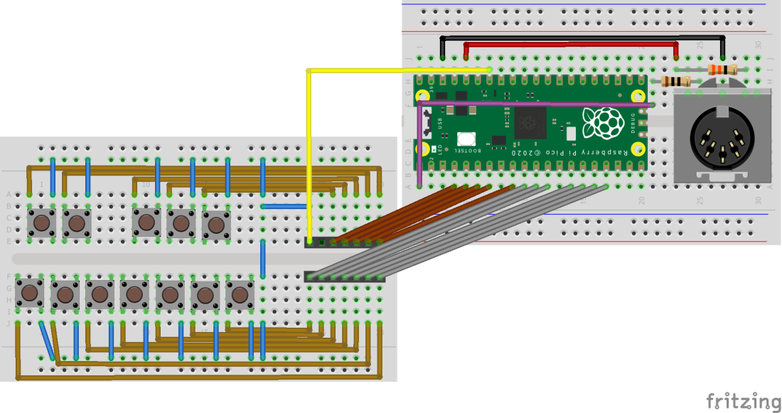
This circuit is essentially hooking up 12 buttons formed to represent 12 notes of a piano keyboard to 12 input pins for the Pi Pico, in this case using GP2 to GP13.
The simplest way to do this would be to tie the other side of each button to either GND (if the inputs are configured for PULL_UP mode) or to +3.3V (if configure for PULL_DOWN mode).
Allowing for the use of TX on GP1, there are enough IO pins to allow 24 buttons to be connected directly – that’s enough for two full octaves of notes.
But I want to eventually have more notes than that. One common way would be to start including additional expander peripherals, but I’m trying to keep things relatively simple. So instead I am treating all 12 buttons in one octave as a single column in a keyboard “matrix” and hooking up the common pin from all the switches to another one of the Pico’s IO pins, in this case GP28.
To add another octave, the switch board must be duplicated and the individual switch connections hooked up to GP2 to GP13, duplicating the links to the first board. Then the common pin needs to be hooked up to an unused IO pin, for example GP27.

Further octaves can be added on a “one extra IO pin per octave” basis until all GPIO pins have been used. In theory, it should be possible to hook up 12 of these “octave” boards to the Pi Pico!
For now though, I’m sticking with a single octave for this first experiment.
The Code
This is using MicroPython once more so follow the relevant tutorials to get it running on your Pico. I’m using the Thonny editor to edit and load code. The code is saved as main.py onto the Pico so that it will run automatically on power up without being connected to a computer.
Caveat: I am still learning Python myself, so don’t expect code of any significant quality!
There are two key functions for this code:
- Setup and repeatedly scan the keyboard “matrix” to work out which keys have been pressed.
- Use this information to send the appropriate MIDI messages over the serial link.
I won’t go into detail of how to scan a keyboard matrix – there are details and links in one of my previous projects. For this first demonstration, the matrix is really just a single “column” of keys anyway.
The pins to be used for rows and columns (even though there is only one column) are set up in a list at the start and then those lists are used to initialise the Pins into another list called “rows” or “cols” as appropriate.
The columns are the outputs and the rows are the inputs. Ideally, the outputs would be configured in OPEN DRAIN mode which, whilst not directly supported on the RP2 used on the Pico, can be simulated within Micropython. This mode means that outputs have two states: LOW or “not connected”. This provides better handling of multiple button presses whilst scanning the matrix (see this for all the gory details) but at the time of writing the OPEN DRAIN simulation for the Pi Pico in Micropython was literally just a few days old and hadn’t made it into the release image yet, so I simply used the standard Pin.OUT mode for the time being. This will only be an issue when I have many columns (i.e. more octaves).
In terms of working out when to play MIDI notes, the simplest thing would be to send a MIDI noteOn when a switch is detected followed by a noteOff some time later. But the more sophisticated method is to recognise the OFF to ON and ON to OFF transitions for each individual switch and send the appropriate message as required. This is the approach I’m taking so there are two lists – playnote and lastnote – that record the new and previous states of each switch. This has the advantage that the keyboard is fully polyphonic.
As it stands the code has a starting MIDI note and will calculate which note to play depending on which switch has been pressed. This means it will only send the standard chromatic scale. It would be possible to maintain a list of specific notes if alternative scales were required.
The actual MIDI handling is as before – using a ustruct.pack of three bytes to construct the actual MIDI messages, which are sent on a hard-coded MIDI channel 1 for now.
The video above shows this driving my Arduino MIDI VS1003 or VS1053 Synth as a stand alone MIDI sound module using its default piano sound on channel 1.
Update: It is now possibly to use the MIDI serial port in CircuitPython. There are details of how to do that here.
Closing Thoughts
Using these simple mechanical buttons on solderless breadboard can be frustrating as they tend to pop out with no warning, so although this is designed to allow the use of several octaves of buttons, I don’t recommend using solderless breadboard to make them!
This is now ready for transferring to simple proto or strip-board I think to test the multi-octave performance of the code.
It is really not stressing the Pi Pico at all yet though, and arguably there isn’t anything here that any other microcontroller couldn’t do. But that is ok. This is still general playing around at this stage.
Kevin


Hi Kevin!
I’ve just started my Pi Pico/Micropython adventures.
I have this code running ok currently with slight edits to the GPIO pin numbers. What I’d like to do is add in some buttons and potentiometers to do other MIDI related tasks. I currently have two buttons and two pots connected ok and can read the adc data from the pots and get the buttons to turn the led on and off.
I am wanting to use one of the pots to change the midi velocity that is sent out.
Can the ADC value be converted to 0-127 and then fed into the ‘midiNoteOn’ definition?
‘uart.write(ustruct.pack(“bbb”,0x90,x,127))’,
change to ‘uart.write(ustruct.pack(“bbb”,0x90,x,velocity))’ and then define ‘velocity’ by reading the pot value, converting it down to the 0-127 range.
As I said, very new and learing the basics currently, thanks for any help you can provide 🙂
LikeLike
Yes – definitely doable and well done for getting that far on your early adventures! 🙂
So, assuming you’re starting with the PiPicoMIDIMatrixDecode.py code, then the changes would be something like the following (apologies if some of this is telling things you already know, I wasn’t sure how far you’d got).
If this is a single velocity for the whole device, then the simplest would be to read the ADC in the main loop and then store the resulting value in a global variable to be used in the NoteOn function in place of the 127 value.
To get the scaling, I believe the Pico’s ADC, although being 12-bit (0..4095), is scaled to a 16-bit value (0..65535) in Micropython? So you need to get the 16-bit value (range 0..65535) down to a 7-bit value range (0..127). This is basically a “divide by 512” operation, but in many computer languages, this type of “divide by a power of two” is quicker if done as a “bit shift” – so /512 is the same as >>9 if I’ve got my maths right (I always have to check!). I’d use a bitshift in Arduino C, but in python I doubt it would make much difference so a simple divide should be fine. Note that I think the default in python would give you decimals, so you need to make sure you only get integers with no decimal parts to use with MIDI.
So, I’d so something like the following in the main while True: loop and then use that velocity value in the noteOn function.
velocity = int(adc.read() / 512)
Which I think should give you a 0..127 value you could use directly in MIDI (as I say, if I’ve got my sums right).
Note that if you want a global volume control, MIDI also has the concept of a “master volume” control change message, but that relies on your receiving synth respecting it of course, but that is another way to do something similar in your case. Key velocity allows each note to have a different velocity. Master volume control is literally controlling the whole device volume (or at least the volume of that MIDI channel’s sound generation). That is a different type of MIDI message – 0xB0 = Control Change rather than 0x90 = Note On, and the first parameter is the Control to change, so you’d need 7 which is “channel volume”.
So an alternative might be to write a VolumeControl function that does something like the following:
def VolumeControl (vol):
uart.write(ustruct.pack(“bbb”,0xB0, 0x07, vol))
But you have to watch out when you call it. It would swap the MIDI channel if you called it every time, so in your main loop you’d need something like:
vol = 0
while True:
newvol = int (adc.read() / 512)
if (newvol != vol):
vol = newvol
VolumeControl(vol)
That kind of thing – so it only sends it when it changes.
All of this is only applying to MIDI channel 1 (the 0 in the 0x90 or 0xB0 commands). For different MIDI channels, that 0 can be any of 0 to F (i.e. 0 to 15 in hex) for MIDI channels 1 to 16. So, for example, to change the volume of a drum channel, which is usually channel 10, you need to send the MIDI command 0xB0 + CH – 1 = 0xB9.
Let me know how you get on!
Kevin
LikeLike
Yes that worked perfectly, I added a ‘print’ to see the readout of that velocity value and I’m getting 0-127 and that value is getting sent out via midi. Although the two synths I’ve tested on don’t respond to the value, only if it is 0 I get no sound, all other values it is what ever the synth is set to. But that’s likely a synth setting I can look at.
The further info is very useful, for the second pot I’d like to use it for something like a filter or other setting in the synths, again I’ll need to look at the specific synth and see what I need to send to it.
My next challenge is to use the rocker switch I have in the unit to select another set of midi notes different to the default values 🙂
LikeLike
Great! There is a CC message that is typically used to control filters – I think it is one of the “effects” control messages (google “MIDI Control Change message” and you’ll get a list) – but ultimately as you say it is more down to what control change messages your synth accepts and acts on. That is probably buried in the MIDI implementation chart somewhere…
Do let me know how you get on 🙂
LikeLike
Hi again,
I have been distracted by some other pico projects but the hardware is done and running at this stage. I’ll come back to this and try and get some more functionality going :).
Pics of the controller:
https://photos.google.com/share/AF1QipPNfIGD3mmOWch1iYCZCLMKCshZ8l0V-TZ_oPMaC_7ULrGJJPbINLLnS6jAdBrhTA?key=QnBTODRRSHk1aW1rcTRSNWxZS0k1U3JqWFVPQ0Z3
LikeLiked by 1 person
That’s looking really good! 🙂
LikeLike