My previous experiments with Arduino tone() polyphony have led to a curious tangent, following some comments on a hackaday post featuring my original project that compared my project to Top Octave Generators. This describes how I used the same principle to create a simplified (and not very accurate or useful) Arduino Top Octave Generator as a bit of fun.
As I say, this is just a bit of playing around. If you want to know how to do it properly, there is a project that describes how to use an AVR chip with some clever coding to provide a complete, pretty accurate, replacement for the specialist chips used in organs and string synthesizers from the early days of electronic music. You can read about it in full on the following:
- Ask Hackaday: How do you DIY a Top Octave Tone Generator
- Ask Hackaday Answered: The Tale of the Top Octave Tone Generator
- AVR Top Octave Tone Generation
- Adventures in Top Octave Tone Generation
Warning! I strongly recommend using old or second hand equipment for your experiments. I am not responsible for any damage to expensive instruments!
If you are new to Arduino, see the Getting Started pages.
Parts list
- Arduino Uno
- 12x 10kΩ resistors
- 12x button switches
- Amplification
- Breadboard and jumper wires
The Circuit
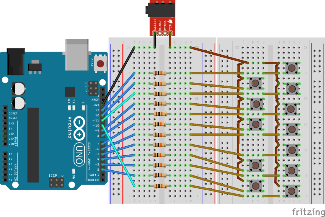
Rather than mess about with buttons and solderless breadboard yet again, I actually used the simple (diode-free) one-octave stripboard I built for Arduino Tone Polyphony – Part 4, but here I’m using it in a different way. The common pin from the switches becomes the common audio out which in theory would go through a passive mixer. But as the switch matrix is pre-built, I’ve added the mixing resistor before the switch rather than after it, as you might normally expect to see.
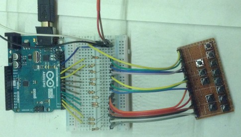
I’ve experimented with a number of mappings of IO pins to switches, for reasons that will become clear shortly. In the above diagram, you can see that most are consecutive apart from pin 10 becoming the “low C”. Another arrangement (shown in the photo) has pins 10 and 11 becoming A# and B. Read on to find out why.
The Code
A real Top Octave Generator would be creating the frequencies required for the highest octave (e.g. C7 to B7) and then using divider circuits to half them each time a new octave is decoded. This project takes that idea but is running with the much slower code from my previous Arduino Tone Polyphony projects, so I’m treating C5-B5 as my “top octave” for the purpose of these experiments!
The core principles behind the code are exactly the same as described in Arduino Tone Polyphony – Part 5 but the oscillators are running all the time – there is no MIDI detection and nothing monitoring switches. The keyboard will be purely mechanical in this case, connecting up the oscillator source to the output when a key is pressed.
I am using two of the timers on the Arduino to generate PWM outputs so I can trim down the number of tones required to be produced by the interrupt routine to 10. This means that I can run with a 20 uS TICK. You may recall from part 1 that 20 uS was ok from a frequency point of view, but meant that the MIDI/loop handling was being starved of processing power with 12 tones, but it pretty much worked ok for 10 at 20uS.
There are three timers on the Arduino Uno (ATmega328) and I plan to use them as follows:
- Timer 0 (8-bit): use for the 20uS TICK with an interrupt on match with COMPARE A. This will override the use of the timer for the Arduino delay() and millis() functions.
- Timer 1 (16-bit): use for a 50% duty cycle output, toggling OC1B on pin 10 on timer match with the counter.
- Timer 2 (8-bit): use for a 50% duty cycle output, toggling OC2A on pin 11 on timer match with the counter.
I’m calling this PWM and I’m using two of the PWM output pins associated with the timers, but in reality I’m using them in CTC mode – the “normal” counter mode – rather than PWM. As the output pin is toggled on timer match, then I need the timer to count twice for any given frequency – once for the HIGH value and once for the LOW. This means that whatever counter value is calculated for a specific frequency has to be halved so it counts twice as fast as required.
There are lots of detailed comments in the code for the initialisation of the timers, so I want repeat that detail here, but the key thing to determine is what variation of prescaler and timer counter value will give a specific frequency. Once again I resorted to spreadsheet modelling, with the required frequencies for the 12 notes (C5 to B5) listed, then for each prescaler value (1,8,64,256,1024 for Timer 1, 1,8,32,64,128,256,1024 for Timer 2) I calculated the nearest counter value to give that frequency using the formula (from the ATmega328 data sheet):
counter = (CLOCK / (Prescaler * Freq)) – 1
For example, for the 16MHz clock on the Uno, testing a frequency for C5 (523.25Hz) with the prescaler value of 8, means that the nearest counter is a 16-bit value, of 3821.
Then plugging this value back into the reverse calculation will give us the resulting frequency that will be produced from the rounded value:
freq = CLOCK / (Prescaler * (counter + 1))
For the same example (16MHz, prescaler=8, counter = 3821) that gives us a frequency of 523.286Hz which is only out by 0.036 which is pretty good. Filling these in for the whole table means I can get a feel for which values give the most accurate “integer rounded” frequencies, looking something like the following:
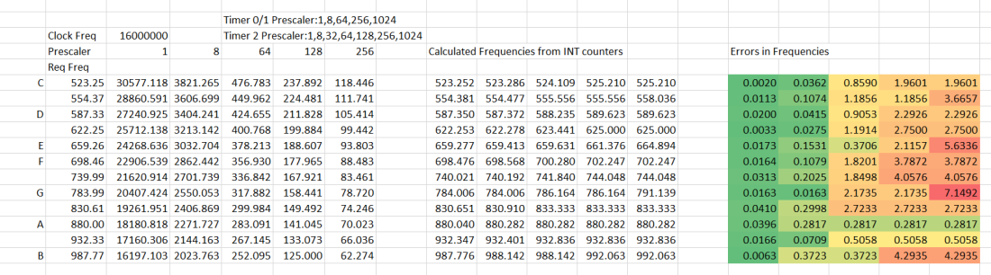
Ideally, I’d be using any the “most green” values, but these all require a 16-bit timer. For an 8-bit timer, I can only use results where the counter value is less than 512. Recall that the counter will be counting twice for each pulse, so I can go up to two counts of 255.
The first approach, and the one in the video, chose the two most accurate frequencies from the above and used the interrupt for all the rest. This resulted in using Timer 1 for the lowest C and Timer 2 for A, hence the odd routing from IO pins to switches in the circuit diagram.
I tried another approach too – rather than going for the most accurate frequency according to the above, the second approach looked at the least accurate frequency from the timer interrupt. This resulted in choosing A# and B for dedicated timers. But to me, that sounded worse, so I kept with the first try.
Cutting down the number of tones.
One of the reasons for using the timers was to reduce the number of tones requiring calculating in the interrupt routine. A few changes are required to the code to allow this to happen and you can use these in any of the previous project parts that don’t assume a one-key-to-one-frequency mapping to get better accuracy there too if required. Here is what you have to do.
- Change NUM_TONES at the top (I’m using 10, but you could drop back to 8 or 6).
- Update PORTBMASK as required. Note that you will have to still use consecutive pins unless you start getting fancy in the interrupt routine. Also, if you take pins out of PORTBMASK then you’ll have to explicitly set their direction using pinMode as required. Note if you drop down to 6-note polyphony then you won’t need to use PORTB at all.
- If you are using a version of the code where there is a one-to-one frequency to pin mapping, then you’ll have to change the number of counter values listed in the freq[] array, but if this is the case you’ve also just dropped down on the number of supported keys too! If you are using one of the versions of code that allows you to play more notes than oscillators, then this will be ok.
- In the interrupt routine you may have to account for alternative uses of IO pins not being used for sound generation. I already do this for PORTD so it doesn’t mess with the serial port RX/TX (see the code). If you are not using consecutive pins, then you might need slightly more fancier bit manipulation. I had to do this in my case as I needed to “skip” over IO pins 10 and 11 to use their PWM outputs.
In the code, you can see I’m using the “adjust high/low frequencies” trick from part 5 to allow for more frequency correction too.
The result is ok for C5-B5 but a few of the notes are still a little off. But that is probably the best that I can do whilst keeping the code relatively understandable, so I’ll leave it there for now.
Closing Thoughts
This was just a bit of a “what if” experiment. I certainly never expected it to match the apparently great results obtained by “aprimatic” from APWizardry here, which really does seem to be pushing the AVRs to their limits.
It was particularly interesting to read about using the two additional timers for PWM to allow the code to cope with 10 tones without having to hardware-mod the Arduino to run at 20MHz instead of 16MHz. Unfortunately if you wanted to try that yourself the published code from APWizardry was corrupted in the forum comments, so that will have to remain an exercise for the reader…
I have been studying that code and am fascinated by the “loop stores the actions in a buffer whilst the interrupt routine takes the actions on cue” approach. That is something I might explore a little more myself at some point. I’m pretty sure that I can improve on my own code by doing something similar without resorting to assembler. It would be nice to manage a faster TICK, but I’m not trying to get it up to the “octave 7” frequencies of the originals!
There are also AVRs with more timers, so it may be possible to have more hard-coded PWM outputs and even less work required in the interrupt routine.
One reason for doing this is to try the divider approach to having lower octaves too, so I have some binary counter chips on order that I hope to use to give me another couple of octaves of notes.
At the end of the day though, this is all good fun, but with the arrival of so many more powerful microcontrollers now (not least of which the Raspberry Pi Pico of course) getting audio frequencies out of 12 digital pins should be a lot easier these days. So I’ll probably explore that at some point too.
Kevin
