In this final (for now) part of my Arduino Tone Polyphony project I’m returning to part 2 which was creating a stand-alone, full 12-note polyphonic tone keyboard with an Arduino Uno and committing it to an Arduino Shield using a proto-shield.
Warning! I strongly recommend using old or second hand equipment for your experiments. I am not responsible for any damage to expensive instruments!
These are the key tutorials for the main concepts used in this project:
- Arduino tone()
- How to build an Analog Mixer
- Arduino Port Manipulation
- Arduino Analog Input
- Read Multiple Switches using ADC
If you are new to Arduino, see the Getting Started pages.
Parts list
- Arduino Uno
- 12x 10k resistors
- 12x 1k resistors
- 6x 2k resistors (mine measured out at 2.1k)
- 1x 10uF non-polar capacitor
- Audio amplification
- 1x PCB mounted SPST switch
- Proto-shield
- Headers and jumper wires
The Circuit
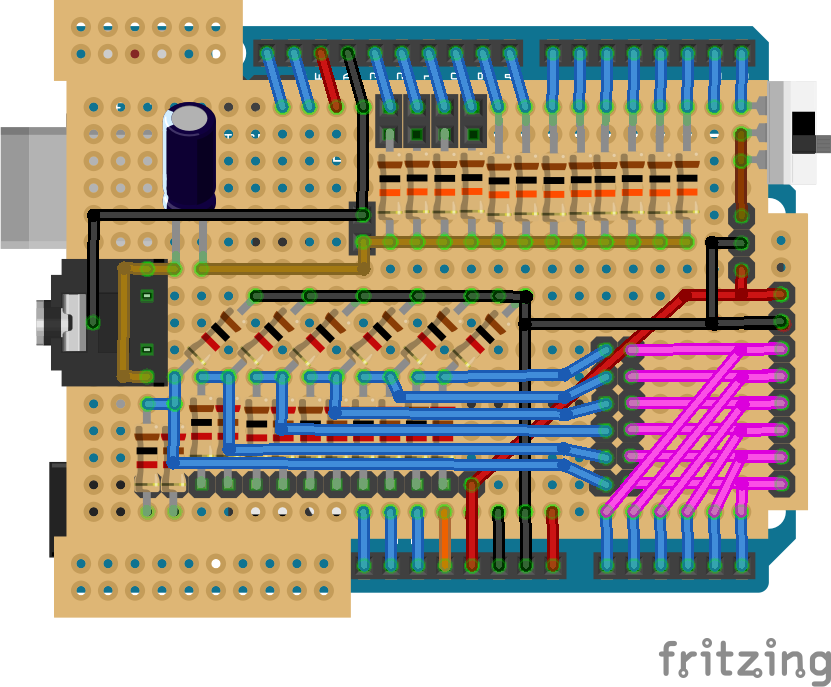
The detailed explanations of the parts can be found in part 1 and part 2, but roughly this includes the following sections.
Note that although a simple connection to a jack socket is shown above, I’ve not implemented that bit yet. I plan to do some experimenting to see if a filter of any kind would be useful, but if you’re not bothered about that, you can wire up the socket as shown above.
As it stands, I’m just taking the audio off that jumper in the mixer section for the time being.
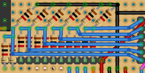
The Passive Mixer circuit:
There are 12 connections to digital IO pins via 10k resistors to a single jumper that provides the mixed audio out (bottom left). Four of the IO pins are via jumpers, so I can if I wanted drop this down to an 8-output shield and use four of the IO pins for something else. These are the IO pins that are used for SPI peripherals. You can skip these jumpers if that isn’t important.
For more details, see part 1.
MIDI Input Connection:
I’ve included a MIDI in connection for 5V-GND-RX with RX via a sliding switch. This is entirely optional, but does allow me to use the shield for the MIDI related tone polyphony projects too (such as described in Part 3).
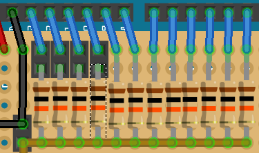
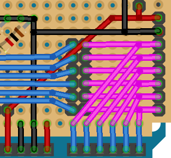
Switch Decoding:
This is the resistor network providing 6 instances of a two-switch detection circuit, one for each analog input, as described in part 2.
After thinking through a few options, I opted for the arrangement shown above as it seemed the simplest wiring setup for me. However it does mean that the order of the switches is from right to left, not left to right. So starting from the right, the pins related to the following:
- 5V power (right most pin)
- A0 switch 1
- A0 switch 2
- A1 switch 1
- A1 switch 2
- … and so on until …
- A5 switch 2 (left most pin)
Analog Connection and Breakout:
The final section I’ll describe here is the connection of the switch network to the analog pins. Again as has become a common pattern on some of my shields, I’ve broken out all six analog pins to jumpers, alongside 5V and GND, and then linked the switch resistor network to them via a series of jumpers. This means that should I want to I can disable the links to the switches and have the analog pins available for use.
If this isn’t important to you, you can simply connect the outputs of the resistor network directly to the analog inputs.
As shown, the analog pins go from A0 at the top to A5 at the bottom.
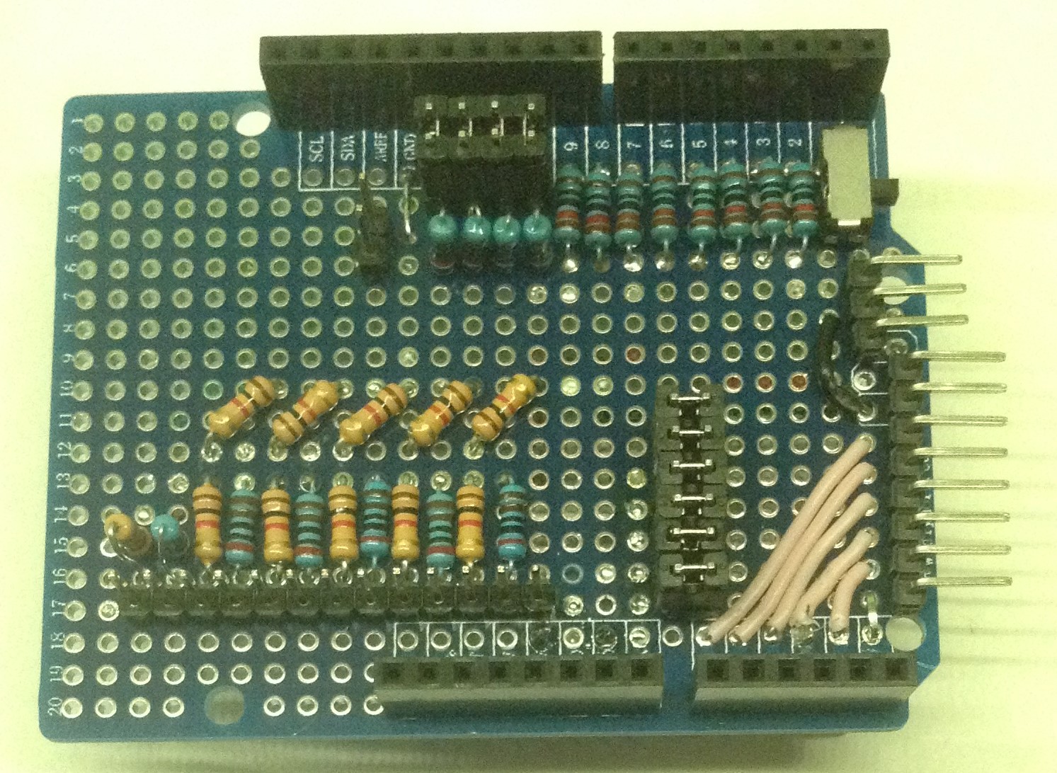
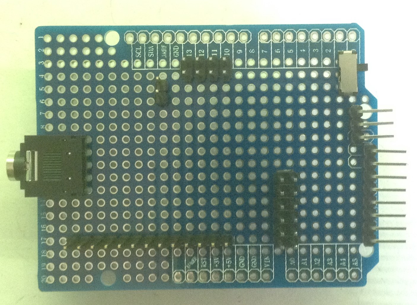
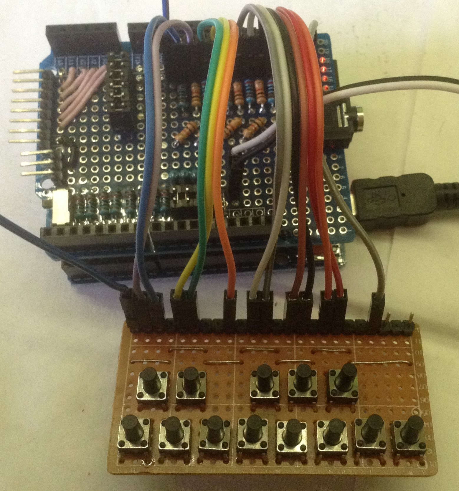
Build Photos
Having walked through the main sections of the circuit, here are some photos, complete with my dodgy soldering, part way through the build of the various sections. Note that I started by positioning the various headers, sockets and jumpers to get the best spacing on the board.
Once that seems ok, these are soldered in. Note that although the jack socket is shown in the photos, it isn’t soldered on yet. It is just there for positioning until I decide what to do with it.
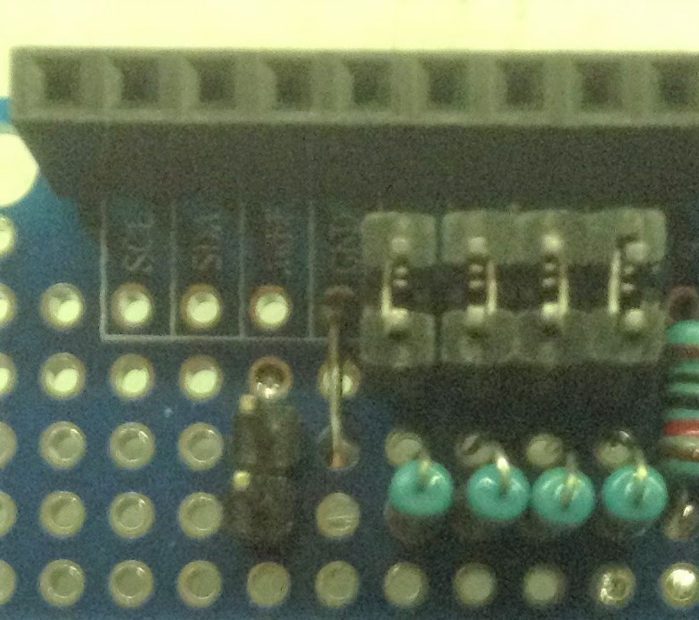
First to go in are the resistors for the passive mixer section. The bottom legs of each resistor are used to make the common “out” connection to the audio out jumper and the four resistors connected via jumpers were installed vertically to keep the bottom legs all in line.


Followed by the pairs of resistors for the switch network. The 1k resistor is on the left, 2k on the right for each pair. Notice again how the first two are installed vertically to allow space for the jack socket. Remember the last pin on the right is the 5V connection.


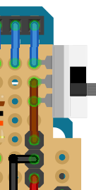
I wired up the analog pins by using a series of wires on the top of the board to link to the breakout header pins, then more wires on the underside of the board to connect the breakout header pins directly to the jumpers to connect to the switch network.
At this point I’ve also wired in 5V and GND connections for the breakout headers, but not connected them to anything yet. Recall that both the analog breakouts and the (optional) MIDI link need a 5V and GND connection to be useful.
You can also see I’ve tied the RX pin of the MIDI jumper to the bottom two pins from the SPST switch too. The third pin of the switch is linked to the Arduino’s RX pin.


The final six resistors complete the switch resistor network and all need tying back to ground. I link them to the GND link from the analog pin breakout headers. In order to allow for the jack socket in the future, the last resistor, corresponding to the vertical pair of switch resistors, was mounted on the underside of the board.
At this stage we can also provide the last link up – between the analog pin jumpers and the analog outputs of the resistor switch network pairs. These links are all made on the underside of the board. Note that in the photo below, the 5V wire is still not connected to anything.


The final step is to tie in the GND and 5V connections to the Arduino’s GND and 5V pins on the shield. I’ve linked them to the “power” headers at the bottom of the shield.
If it hasn’t been done already, we also need to connect the audio out header pins to GND too. I connect those to the GND at the top of the shield. The plan is to keep the analog and switch circuitry using the GND at the bottom and anything audio output related using the GND from the top, although the jack socket is still unconnected (and unsoldered) for now.

I always intended to use it with one of my hand-built “keyboards” from my Pi Pico MIDI Matrix Decode – Part 2 project, but since adding diodes (long story, explained here) they are no longer suitable for use here as the diodes prevent the current flow in the direction I need here.
So I built another diode-free “keyboard” for use here, but you can link up to switches however you like as long as they all have a common 5V feed to one side of the switches and the other side links to one of the pins on the shield.
The Code
All the code for this is as described in part 2. The only change required is to set the order of the switches. As mentioned previous, the switches are numbered from right to left, so assuming they are wired in “right to left” sequence, I went with a trivial mapping as follows:
// Define which of the notes are played by the switchs
//
int algOrder[NUM_TONES]={
// A0-1 A0-2 A1-1 A1-2 A2-1 A2-2 A3-1 A3-2 A4-1 A4-2 A5-1 A5-2
      0,   1,   2,   3,   4,   5,   6,   7,   8,   9,  10,  11
};
In my case this meant making sure I’d wired it up to my hand-made keyboard in the right order too – in my case that means swapping pairs of leads over, as the keyboard design always presents a “black note” connection before the lower “white note”.
I’ve also added a 13th key for my build for future use, but that isn’t decoded here.
Find the original code on Github here (and update it for you own key mapping).
Closing Thoughts
Recall the original aim was to emulate the “full note polyphony” of the Oskitone Poly555, but cheating and using a microcontroller. This shield goes a long way to supporting that in a simpler module.
I’d still like to implement this using several Arduino Nanos for a full two-octave “version” of the Poly555, but I’m not sure if that is really worth the effort now I’ve got this far.
Kevin

Great project!
LikeLike