From the first time I put my Raspberry Pi Pico Multi MIDI Router onto protoboard, I thought it would be handy to have a PCB version. This post describes the design process to do just that.
Update:
- Find the Build Guide here: Raspberry Pi Pico Multi MIDI Router – Part 5
Tutorials used in this project:
- Raspberry Pi Pico Multi MIDI Router – Part 2
- Notes on KiCad for PCB design: Arduino Uno Dual Merge MIDI “Shield” – Part 2
If you are new to microcontrollers, see the Getting Started pages.
The Circuit

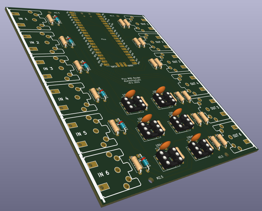
This is the largely the same as the original Raspberry Pi Pico Multi MIDI Router but I’ve allowed for six MIDI IN and OUT ports, so it is using both UARTs and four PIO UARTs.
I’ve also switched 6N138s for H11L1s and adjusted the circuit accordingly. I’ve also used a 3V3 compatible MIDI OUT stage, but haven’t included any buffering – so it is a relatively basic design from that point of view. Power will all come form the Pico via its USB port.
There are no extras. Future enhancements could include buffering and LED indicators for example, a power circuit, and possibly even some kind of hardware IO panel, but I’ve just gone with the basics for now.
PCB Design
I don’t think there is anything particularly remarkable about this design, but here are some notes:
- I’ve used a full Pico footprint, not just headers, so the option to solder a Pico down to the board is there. I’ve also tried to align it so the USB port is accessible at the top.
- I’ve taken a lot more care over positioning, to try to ensure footprints line up nicely.
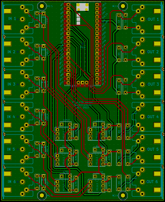
- I’ve used a zone on the rear side to provide a ground plane.
- I’ve tried to avoid having lots of parallel routes, especially on both sides of the board. Where there are tracks in parallel, I’ve tried to run them over the ground plane rather than over other tracks.
- I’ve added four M2.5 mounting holes (same as used with a Raspberry Pi).
- I’ve taken the time to change the more structural mounting holes for the DIN sockets into rectangles and offset them slightly, the hope being that they would give a strongly physical connections to the PCB than the default round ones.
I’ve used the ERC and DRC tools and once again tried a space-model using a black and white printout to see if everything seems to “feel right”.

Alternative Options…
As an exercise, I also had a go a producing a surface mount version, just to see how it might work. The increased capacity for routing on the board also allows me to incorporate a proper output buffer stage by using a couple of 74HCT14 hex inverters as buffers and voltage shifters.
I don’t know if I’ll do anything particular with it, I don’t at present have a stock of surface mount components myself and hand-soldering whilst possible, is not something I’m too bothered about doing right now.
But I have the design and am pretty pleased with how it “looks”. I’ll see how I feel about it once I have a bit more experience building pcbs, but for now, here is the pcb design. It isn’t too dissimilar from the above!

Closing Thoughts
The overall size of this board is 100mm x 122.5mm, so it is a bit more expensive to produce again, but on the back of my last few efforts, thanks to reviews and linking to the Seeed Fusion service again, I have some more coupons to spend, so I’m sending this one off now too.
This would be a neat point to get to with my MIDI router. I’ve not done anything about USB support, but I’ve left the GPIO pins available for further expansion if required.
As mentioned above there are a number of possible enhancements, but I’ve kept everything relatively simple for now, whilst I’m still experimenting with PCB design.
Kevin
