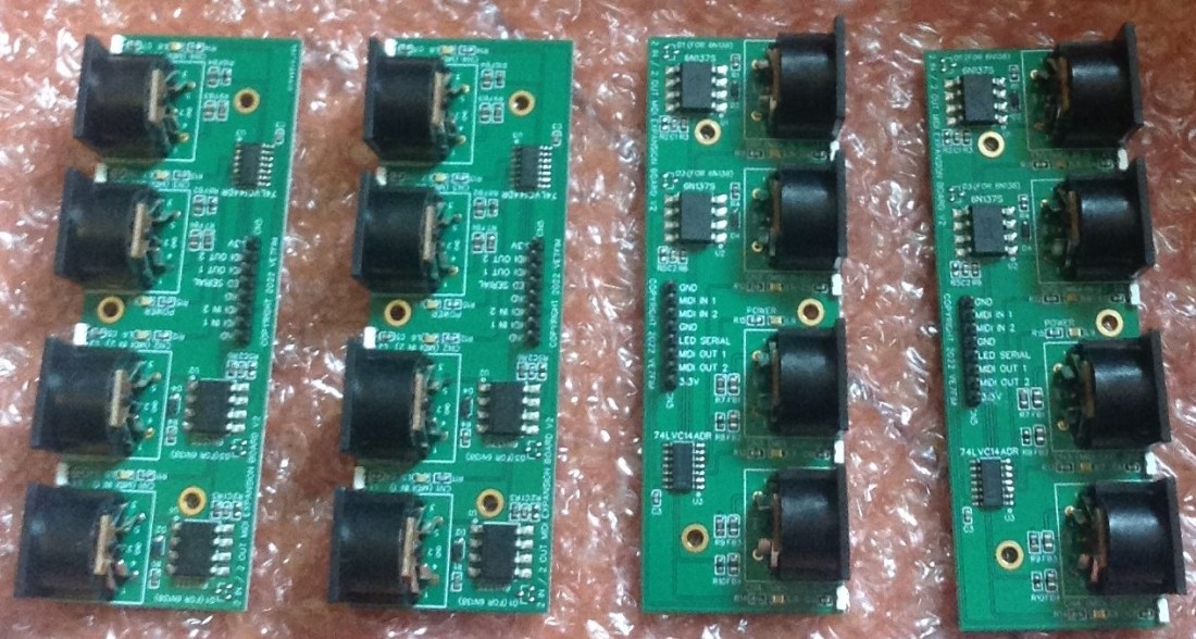
After publishing the details of my diy proto-board version of my Raspberry Pi Pico Multi MIDI Router I got into a conversation with @VE7FIM on Twitter about MIDI boards for the Pico and they very kindly offered to design and build a dual MIDI interface board for me for my Pico. This was back in January and it took a few months for the boards to come through, then there was a second iteration and they sent me some boards back in April.
But I’ve not really done anything significant with them for a whole host of reasons, mostly around not just wanting to just re-do a previous project, wanting to get more of my own synths set up (although I’m still deciding what to do about a mixer), and really wanting to do something that might at least do some justice to the time they spent designing the modules for me.
This is the first step of starting to do something with the modules. I’ve taken my Raspberry Pi Pico Multi MIDI Router and started experimenting with a simple user interface to allow me to configure the basic routes. As regular readers of this blog will know, I tend to work quite slowly in python, so this will take a while to home in onto something really usable, but I thought this first step was interesting enough to put up. So here it is.
Warning! I strongly recommend using old or second hand equipment for your experiments. I am not responsible for any damage to expensive instruments!
These are the key tutorials for the main concepts used in this project:
If you are new to microcontrollers, see the Getting Started pages.
Parts list
- Raspberry Pi Pico
- SSD1306 OLED 128×32 display
- KY040 rotary encoder module
- 2x 3V3 compatible MIDI interfaces (I’ve used one of the neat modules made for my by VE7FIM).
- Solderless breadboard and jumper wires
- MIDI controllers, sources, etc.
- MIDI synthesizers, sound modules, etc.
The Circuit
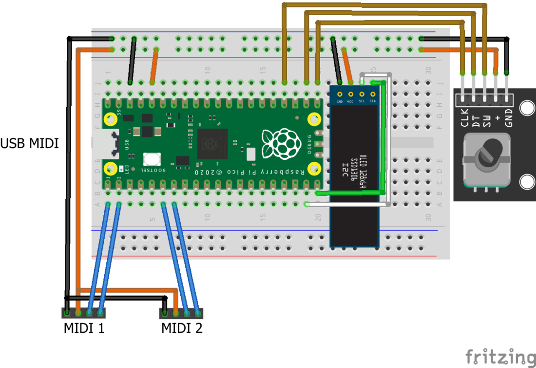
Now if you are following along at home you will need two 3V3 compatible MIDI modules. As I say I’m lucky that I have this great dual-MIDI module built for my be @VE7FIM. In fact they very kindly sent me four to have a play with, but I’m starting with just one for now 🙂
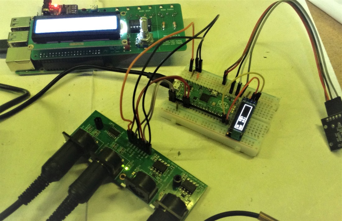
Then of course I needed a source of MIDI data – I used my Yet Another Toy Keyboard USB MIDI Controller in serial MIDI mode.
And for this simple demonstration, I used three MIDI sound sources as follows:
- As a USB host to the Raspberry Pi – my MiniDexed.
- On Serial MIDI 1 (UART 0) my Shruthi synth.
- On Serial MIDI 2 (UART1) my MT-32.
The Code
The core MIDI routing code is pretty similar to my previous router projects. Note that I really wanted USB MIDI though as one of the options and didn’t really want to have to use add-on microcontrollers like before. As I’m only initially working with a dual-MIDI interface, I can use CircuitPython here to do USB and serial MIDI using the Pico’s two hardware UARTs.
Adafruit provide support for the SSD1306 128×32 OLED display via their displayio_ssd1306 library. I’ve also used display_shapes and display_text from the displayio set of libraries.
I want to use a rotary encoder as the main input for the user interface, so that is supported via the built-in rotaryio module.
Whilst these are great for this specific project, the code is very unlikely to be portable across to Micropython should I wish to change in the future as the display support for MP is very different. To expand to more serial MIDI ports, I’ll have to work out how to drive the PIO subsystem of the Pico from CircuitPython… that is something that is already long overdue, but that is also a project for the future.
The following GPIO pins on the Pico are used:
- GP0/1 – UART 0 for Serial MIDI 1
- GP4/5 – UART 1 for Serial MIDI 2
- GP14/15 – I2C interface to the OLED display
- GP16/17/18 – Rotary Encoder switch and encoder
Everything is powered from 3V3 and GND.
The basic idea is to have a two-line display, with IN ports listed at the top and OUT ports listed at the bottom. The encoder is used to scroll through the ports and select an IN port. Then the OUT ports it is going to be routed to can be selected.
The display will be something like the following:
IN    1  2  3  4  5
OUT   1  2  3  4  5

On selecting an IN port:

IN       2
OUT   1  2     4
For USB and two serial ports (UART 0 and UART 1), I’ve used the labels U, 0, 1 as follows:

The code is quite complex, but the main concepts are described below.
The three MIDI interfaces are set up using the Adafruit MIDI libraries.
import usb_midi
import adafruit_midi

from adafruit_midi.note_off import NoteOff
from adafruit_midi.note_on import NoteOn
from adafruit_midi.polyphonic_key_pressure import PolyphonicKeyPressure
from adafruit_midi.control_change import ControlChange
from adafruit_midi.program_change import ProgramChange
from adafruit_midi.channel_pressure import ChannelPressure
from adafruit_midi.pitch_bend import PitchBend
from adafruit_midi.midi_message import MIDIUnknownEvent

uart1 = busio.UART(tx=board.GP0, rx=board.GP1, baudrate=31250, timeout=0.001)
sermidi1 = adafruit_midi.MIDI(midi_in=uart1, midi_out=uart1)
uart2 = busio.UART(tx=board.GP4, rx=board.GP5, baudrate=31250, timeout=0.001)
sermidi2 = adafruit_midi.MIDI(midi_in=uart2, midi_out=uart2)
usbmidi = adafruit_midi.MIDI(midi_in=usb_midi.ports[0], midi_out=usb_midi.ports[1])
I have to import every MIDI object supported by the library otherwise it won’t be able to understand them enough to route them on…
There are a number of different structures in use throughout the code:
- “In ports” and “out ports” are objects used to handle the display of the port labels.
- A screen object has a list of the in/out labels and is used to actually put the labels on the display with certain properties (colour, etc – although this is a monochrome display).
- MIDIRT is the MIDI routing table with a “row” of enabled OUT ports for each IN port.
There are two different set of indexes in the code:
- 0 to INPORTS and 0 to OUTPORTS
- 0 to PORTS, where PORTS = INPORTS + OUTPORTS
The IN ports are listed first in the PORTS list followed by the OUT ports. A set of functions are provided to translate between the two: idx2port(), inport2idx(), outport2idx() – plus a function to work out if a port index is an IN or OUT port: isInPort().
There are a set of functions for turning on or off the port labels to create the required display: portOn(), portOff(), portToggle(). These all act on the appropriate port label object in the screen structure. The idea is that ports that are enabled are displayed, but ports that aren’t are not shown. But these functions are pretty basic and only really used on initialisation.
There are a more complete set of equivalent functions that do the same but are “cursor aware”. This is because in order to be able to select a port to act on, there needs to be some idea of a cursor on the screen that is controlled by the encoder. I’ve opted for a highlighted block rectangle to show which label is currently “in focus”. So when working out if a port should be “on” or “off”, the final appearance has to be able to work out of that particular port is currently “under the cursor” or not. This makes the logic a little complex, but essentially works as follows:
displayPortOn (pidx):
  if cursor == pidx:
    Set label itself to BACKGROUND colour
    Set label background to FOREGROUND colour
  else:
    Set label itself to FOREGROUND colour
    Set label background to BACKGROUND colour

displayPortOff (pidx):
  if cursor == pidx:
    Set both label and background to FOREGROUND colour
  else:
    Set both label and background to BACKGROUND colour
There is a displayUpdate() function that basically calls displayPortOn() or displayPortOff() for each port in the screen structures, but it has to be aware of the two modes of operation, which are:
- Scrolling all ports, ready to select a port to act on (“normal mode”).
- Having selected a port (only IN ports are currently supported), allow the selection and deselection of which ports it will route to (“select mode”).
The display function will run through all IN and OUT ports in normal mode, but will only display the selected IN port if in select mode.
There is a function to update the position of the cursor. That too has to be “mode aware”. When in normal mode it will scroll through all IN and OUT ports. When in select mode, it will scroll through the selected IN port and all OUT ports only. Selecting the IN port again will take the system back out of select mode into normal mode again.
Note that the rotary encoder’s switch is used to select the port that is currently under the cursor in both modes.
MIDI routing itself is handled in a very similar manner to my previous project, but the routing table is a lot simpler. It has no knowledge of MIDI channels or commands, it just allows routing between MIDI ports.
There are two functions that will take the current routing table and turn it into a screen structure ready for display, and vice versa. These are routes2display() and display2routes(). These are used either side of the selection of a port in normal mode, so that the latest routing table is shown on the screen for editing, and then saved back once editing is complete.
The main control loop runs as follows:
While True:
  receive USB MIDI messages
  receive serial 1 MIDI messages
  receive serial 2 MIDI messages
    IF message received THEN routeMessage

  IF encoder button pressed:
    IF in select mode:
      IF cursor is on an IN PORT:
        display2routes()
        disable select mode
      ELSE
        toggle the selected port
   ELSE IF not in select mode:
     enable select mode for selected port
     routes2display(selected port)

  IF rotary encoder turning RIGHT
    cursorUpdate (incrementing)
  ELSE IF rotary encoder turning LEFGT
    cursorUpdate (decrementing)

  displayUpdate()
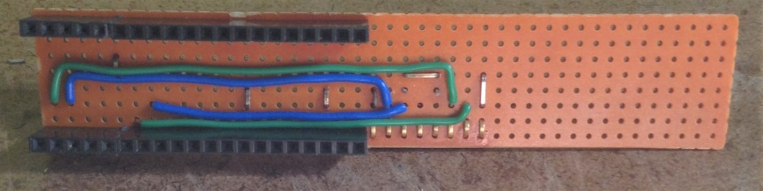
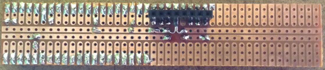
Bespoke Pico Carrier Board
This is a DIY “Pico module” that can be plugged into one of these dual MIDI modules and allows me to use it without a solderless breadboard. I’ve hacked it together from a piece of cheap protoboard, but it is the same circuit as shown above.
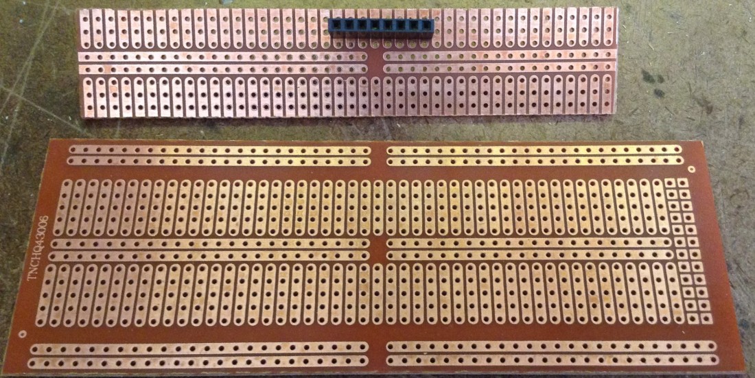
I’ve used the slightly hacky technique of bending over the legs of some extended headers in order to allow me to mount the headers on the solder side of the board…

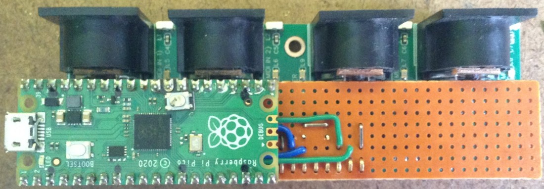
The basic UART and power connectors between the Pico and the MIDI module.
A header has been added for the SSD1306 OLED display and the rotary encoder placed on the end.
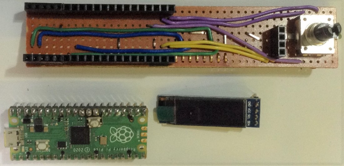
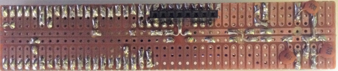
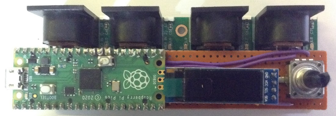
This is quite a nicely self-contained twin serial/USB MIDI router now.
Closing Thoughts
Whilst this really doesn’t do justice to that MIDI module, it isn’t a bad start. One thing I’ve not utilised yet, is an onboard RGB LED for each MIDI port. It would be great to have some kind of colour indication on each port related to the message being routed.
The code should in principle extend to 6 ports, allowing me to use three of these dual modules, but I need to get PIO serial ports working in CircuitPython first. If I can though, it would be great to mount the modules in a panel in a rack.
And it would be nice to make the routing a little more sophisticated. Options for further expansion include:
- Using either an IN or OUT port as the starting point for editing – currently only IN ports are supported.
- Adding some means of filtering by MIDI channel.
- Adding some “proper” MIDI merging functionality – at present it is just at the level of “MIDI message” that’s all.
And I’ve done nothing to test the performance of this, and I might still end up trying to do something directly in C with the Pico SDK.
So whilst this all feels like a really good first step, there is still a long way to go before it could be useful I think. But either way, many thanks to @VE7FIM for sending me these modules. They are great!
Kevin


