Having prototyped the idea of a hardware user interface with my Zynthian in Zynthian Revisited this posts develops a DIY IO board for use with a Raspberry Pi to make connecting everything a little neater. If I like it I might see if I can turn it into a custom PCB.
Eventually I’d like a full stacking module that I fix behind a panel in a rack.

Warning! I strongly recommend using old or second hand equipment for your experiments. I am not responsible for any damage to expensive instruments!
These are the key tutorials for the main concepts used in this project:
- Zynthian and Clumsy MIDI
- Waveshare 4″ HDMI LCD for Raspberry Pi
- Zynthian UI Users Guide
- Zynthian Configuration Users Guide (Wiring Layout)
- Zynthian Forum: “Encoders directly to the GPIO of the Pi 4”
If you are new to microcontrollers, see the Getting Started pages.
Parts list
- Raspberry Pi 3 or 4 with SD card, PSU etc.
- Waveshare 4″ HDMI LCD for Raspberry Pi.
- RPi proto PCB – I used the Breakout Pi Zero from ABElectronics.
- H11L1 optoisolator.
- 6-pin DIP chip socket.
- 1x 220Ω resistor.
- 1x 1kΩ resistor.
- 1x 1N914 diode.
- Mini to full HDMI lead.
- 4x KY-040 rotary encoder modules.
- I2S Audio DAC (e.g. PCM5102).
- 5-pin DIN MIDI socket.
- Header pins.
- 40-way GPIO socket.
- Jumper wires.
The Circuit

I’ve use a prototyping board from ABElectronics that I think is a relatively common design. You have to check the GPIO connections, as there isn’t enough space on the breakout for all GPIO to be hooked through to the prototyping area. I’ve seen some boards that don’t connect GPIO24 and some that don’t connect GPIO26. My board, as shown above, is the latter, so I need one jumper wire round to the GPIO connector directly.

I have another, unverified, design for an Adafruit “full size” proto board, but that has a different GPIO map to this one, so I’m not including it here to save confusion!
Here are some photos of the build steps, but the general sequence for me was:
- MIDI circuit passives on the underside of the board.
- Socket for the opto-isolator.
- Rest of the MIDI circuit passives on the top of the board.
- Single row header pins.
- 3V power and GND links.
- Rotary encoder signals (leaving the one that connects to the GPIO dangling for now).
- I2S signals and 5V link.
- GPIO connector.
- Final rotary encoder signal to the GPIO header.
WARNING: I got a couple of things wrong, so you might want to fix at if you are following along with your own design!
First, I was planning on mirroring the pin format of my KY-040 encoder modules, but I got the VCC and GND links the wrong way round on my protoboard! I did think about trying to fix it, but decided I could live with it.
This means that my encoder pinout is:
- GND – VCC- SW – DAT – CLK
But the pinout of the headers on my board are:
- VCC – GND – SW – DAT – CLK
Secondly, as I was renumbering the GPIO to make routing on the pcb easier, I forgot that GPIO17 maps over to Wiring Pi pin 0, which seems to cause problems in Zynthian. So I had to swap to GPIO4 part way through.
Thirdly, and I’m still not quite sure how I managed this, but might be related to the confusion over GPIO17 and GPIO4… I managed to wire up one of the I2S links wrong. I connected it to GPIO4 rather than GPIO18!
So some of the photos you’ll see are wired incorrectly, but I’ll point that out as I go!

I’m just testing the basic layout of the headers and socket.


The MIDI circuit passives on the underside of the board soldered to the holes underneath where the 6-pin DIP socket will go. As the socket will go over these so it is important to trim off any protruding wires/leads as close to the PCB as possible.
Note that one of the leads from each of the capacitor and resistor go through the same hole to both connect to the VCC pin of the socket. Also, be sure to get the diode the right way round (that catches me out more often than it should!)

The top-side links and pull-up resistor complete the MIDI circuit for the time being – all that remains are the header pin connections out to the DIN socket.


The main GND and 3V links.
WARNING: As mentioned above, I got the GND and 3V connections mixed up for my rotary encoders! You might want to fix that – but I decided to live with it (as I didn’t spot it until I’d finished most of the board).
At this point I soldered on the pin headers for the MIDI socket, DAC board and rotary encoders in the positions shown at the start.
Note at this point I could also have soldered links between the top and bottom encoder pin headers to connect VCC and GND, but I didn’t, so I ended up doing those later. But if you’re following along this might be a better time to add those now.

The main rotary encoder signal connections.
WARNING: Notice the mistake, using GP17 rather than GP4. I had to fix that later!

The DAC connectors: three I2S connections and 5V.
WARNING: Notice the next mistake: having got GP17 wired up by mistake, I then went and linked the DAC to GP4 rather than GP18…

At this point I added the GPIO connector and after some initial testing, realised my mistake and corrected it. You can also see I’ve plugged in the H11L1.
WARNING: I used the GPIO connector that came with my breakout, but with hindsight, I’d have probably used one that gives me more separation between the Pi and the board. I recommend you test the height of things yourself prior to soldering…
.

I needed to link the GND and 3V for the two rows of encoder pins together. I could have done that earlier, but forgot, so ended up doing it at the end.
So after a bit more testing (specifically making sure things like power and ground don’t erroneously connect and so on), this is the final “stack” for now.


I’ve added some extra GPIO spacers to allow for space around the heatsinks on the Pi 4 and space for the header connections to the IO.
Eventually I want to fix all this is a large “stack” that can sit behind the screen, mounted into a panel so additional height doesn’t really matter to me as long as it is all within the physical footprint of the screen.
There are many options here, so basically do some test physical builds to see what works for you.
The Code
Everything is the same as used previously apart from the new GPIO numbering.
So to recap, this is the hardware configuration I’m using.
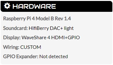
And recall, I’m using the following “advanced” display configuration too:
- Add swapxy=1 in the dtoverlay line.
- Set display_rotate=1.
- Then calibrate the touchscreen.
This is the updated GPIO map I’m using.

Giving me this “Wiring” configuration in Zynthian:

Closing Thoughts
This seems to work. It would be nice to make some custom leads for the encoders, DAC and MIDI to allow a smaller gap between the IO module and the screen, but this would be ok if this is what I end up with.
Using the AB Electronics proto board means all components are easier to acquire, but I think I’ll see if I can make a custom “Zynthian IO” board. If so, I might be able to use right-angle header pins for the connections, meaning it could sit more closely to the screen.
And if I remember to use a longer set of 40-way GPIO headers, then I could optimise the other gap too.
I like my Clumsy MIDI board a lot, but for Zynthian this is a more optimal solution I think. Eventually I’d like to build the whole lot behind a panel, probably as one of my CD Rack Synthesizer Projects.
Kevin
