I’ve finally gotten around to having a play with rotary encoders. It has been on my “to do” list for a while, so I thought I’d start with a rotary encoder version of my Arduino MIDI Button Controller which can select a voice and send the corresponding Program Change message out over MIDI.
Warning! I strongly recommend using an old or second hand keyboard for your MIDI experiments. I am not responsible for any damage to expensive instruments!
These are the key Arduino tutorials for the main concepts used in this project:
If you are new to Arduino, see the Getting Started pages.
Parts list
- Arduino Uno
- 1x rotary encoder “breakout” (switched encoder type)
- 1x 7-Segment Display module
- I used a HT16K33 based one like this one from Adafruit
- Another option might be this one from Sparkfun (untested)
- One of the Arduino MIDI Interfaces or Ready-Made MIDI Modules
- Breadboard and jumper wires
The Circuit
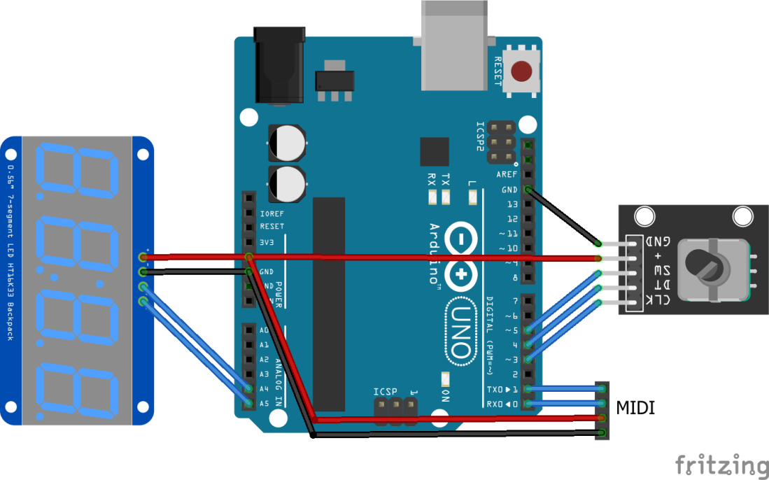
Once again (like my original button version) I’m using a HT16K33 based I2C four-digit display. These are so easy to code for and there are a range of libraries available to use to drive them. It needs to be connected to the I2C connections on the Arduino as follows:
- C or CLK -> SCL on A5
- D or DAT -> SDA on A4
They also need 5V and GND.
The rotary encoders I’m using look like the one in the Fritzing diagram. They have five connections as follows:
- CLK – “Encoder A” – to an IO pin
- D – “Encoder B” – to another IO pin
- SW – the encoder’s switch functionality – to another IO pin
My breakout has pull-up resistors on the D/CLK lines to VCC, hence why the board requires a VCC connection, and a switch that connects to GND. The switch will have to be configured in pull-up mode in software as there is no on-board pull-up (although there is a PCB footprint for a surface mount resistor for the switch if you want to add one yourself).
RX/TX/VCC/GND connections are required to power one of the Ready-Made MIDI Modules.
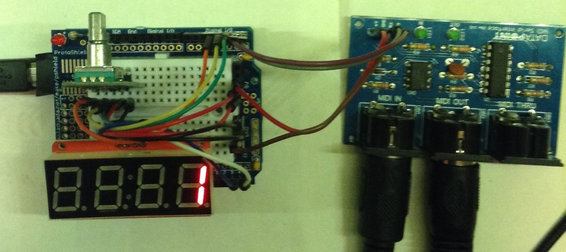
For simplicity, largely due to the fact that all three modules required a 5V and GND connection, I used one of my Adafruit proto-shields as shown below, but it is still wired up according to the diagram above.
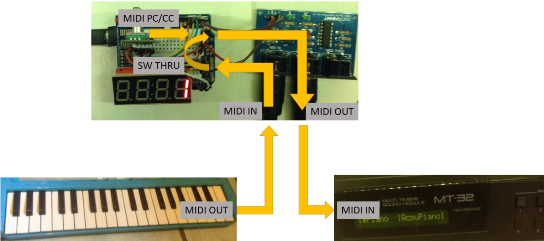
One of the key use-cases is to insert this in the MIDI link between a “dumb” keyboard and a MIDI sound module. Use this way, the Arduino will insert its own MIDI control or program change messages into the MIDI stream between the keyboard and the sound module.
The connections look something like this:
The Code
When I last used a HT16K33 based display, I used the libraries provided by Adafruit. This time I went a slightly different route, opting for the slimmed down HT16K33 library by Rob Tillaart, which you can find here: https://github.com/RobTillaart/HT16K33. This is slightly simpler than the Adafruit code and also smaller but absolutely fine for our purposes here.
For the rotary encoder, again there are many libraries (and I really mean “many”) to choose from, but I’m opting for one of the simpler ones by Matthias Hertel, which you can find here: https://github.com/mathertel/RotaryEncoder.
Both of these libraries can be installed using the Arduino Library Manager.
To complete the set, I need the standard Arduino MIDI library we’ve now used many times before. Serial MIDI is being used, so software MIDI THRU is enabled by default, which is exactly what I need if I want to insert this into the MIDI stream from a keyboard, say.
I won’t go into detail about how rotary encoders work, there is an excellent tutorial here, but you can think of them as a continuously turning potentiometer (sort of). They are great for “wrap around” values or those times when you want to increase or decrease a value, but don’t care where you are starting from in terms of the position of the knob you’re using.
One thing that does need noting however – all the encoder pins need configuring for INPUT_PULLUP mode. Well, technically for my breakout the A/B pins don’t as there are hardware pull-ups on the board, but the library will enable INPUT_PULLUP mode for these regardless (and having internal and external pull-ups isn’t a bit issue). I do have to manually configure the rotary encoder’s switch myself though.
The basic functionality of the main code loop is as follows:
Perform any MIDI THRU handling

Read the encoder
IF the encoded has changed position THEN
   either increase or decrease the stored program number as required

IF the encoder's switch is pushed THEN
   send a MIDI Program Change message with the stored program number

Update the display to show the current stored program number
The only programming quirk that perhaps ought to have a little explanation is how I handle the wrap-around of the program number:
int re_dir = (int)encoder.getDirection();
if (re_dir < 0) {
  prognum--;
  prognum &= 0x7F;
} else if (re_dir > 0) {
  prognum++;
  prognum &= 0x7F;
} else {
  // if re_dir == 0; do nothing
}
As MIDI program numbers are always in the range 0 to 127 (on the wire – visually they are always shown to the user as 1 to 128), then after incrementing or decrementing prognum, I bit-wise AND it with 0x7F which is basically saying “take off the top bit”. So any number in the range 128 to 255 become a number in the range 0 to 127.
The other trick is for switch “debouncing”. I’m using the same software trick I used before here – namely including a counter into the switch handling to ensure the switch won’t be registered as “switched” until the counter times out. We don’t need to go into the details here, you can just accept this as a piece of code that “just works”.
Closing Thoughts
In the video you can see me driving my MT32-Pi in FluidSynth soundfont mode. In this mode each voice number is a General MIDI Voice.
I could have driven the display directly – I’ve done it before – but for this one I wanted to keep things simple. Rotary Encoders are great for this kind of thing though and when using a single one like this, the library I’ve chosen makes it pretty easy to use.
A more sophisticated library exists that allows you to use several encoders all sharing the same pins, so that is something I’d like to look at too.
Kevin

My build jumps 2 digits for every encoder detent. Goes from 1 to 127 in steps of 2. Any thoughts?
Thanks
LikeLike
I don’t know for sure, but there are several different types of encoder, so it might be worth playing with the following line:
RotaryEncoder encoder(RE_A, RE_B, RotaryEncoder::LatchMode::TWO03);
and try some of the other “LatchMode” values described in RotaryEncoder.h (https://github.com/mathertel/RotaryEncoder/blob/master/src/RotaryEncoder.h). It may be that mine is also skipping values, but as I’m not counting exactly and just going for an indication of direction, it doesn’t matter for me in this instance.
Let me know how you get on.
Kevin
LikeLike
Do you have any more info or a link to the “more sophisticated library” that would allow for multiple encoders?
LikeLike
I didn’t look at any specific one, I was just looking at the list of libraries from that “Arduino Playground” link in my post – this one https://playground.arduino.cc/Main/RotaryEncoders/
I just chose what looked like one of the simpler ones for me.
Kevin
LikeLike