Having spent some time recently playing with synth modules it reminded me to revisit my MIDI Patch Button and Arduino Simple MIDI Controller to produce something a little more useful. As a start I wanted up/down buttons to change the patch number and ideally a display to show which number is active. This is how I did it.
- In a follow-up post, I show how to drive a 7-segment display directly.
Warning! I strongly recommend using an old or second hand keyboard for your MIDI experiments. I am not responsible for any damage to expensive instruments!
These are the key Arduino tutorials for the main concepts used in this project:
If you are new to Arduino, see the Getting Started pages.
Parts list
- Arduino Uno
- 2x push buttons
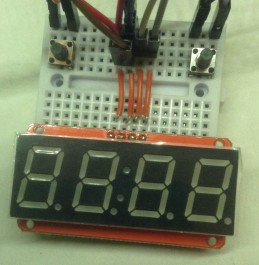
- 1x 7-Segment Display module
- I used a HT16K33 based one like this one from Adafruit
- Another option might be this one from Sparkfun (untested)
- Arduino MIDI Interfaces
- Breadboard and jumper wires
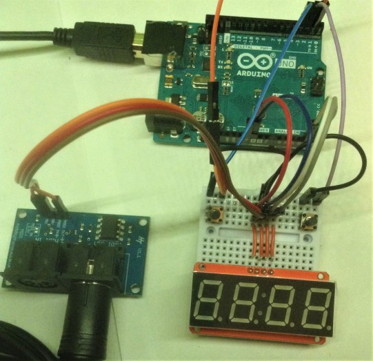
The Circuit
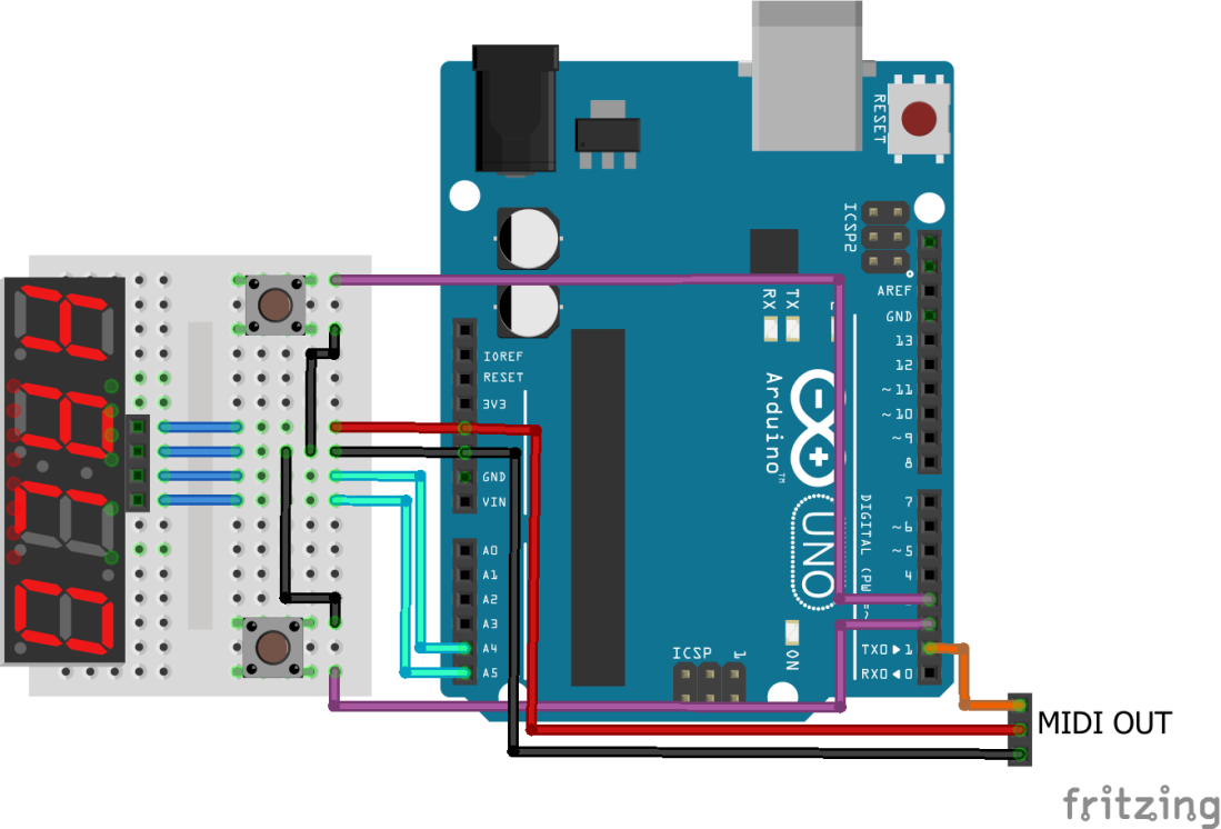
There are many different types of 7-segment display – some with decimal points, some with dots, some with a “:” in the middle. There are also many sizes and colours. The one used in the diagram is actually nothing like the display I’m using or recommending, so is “for illustration purposes only”.
The principles described here apply equally well to any module, but if you are following this as a beginner article, then I strongly recommend getting the “0.56 4-Digit 7-Segment Display w/I2C Backpack” from Adafruit. If for no other reason than Adafruit provide all the code to let you talk to these types of modules very easily, but in principle any HT16K33 based module would do and any other module could be used if you work out how to drive it yourself.
Another option might be the aforementioned Sparkfun module, but I don’t have one of these (yet), so consider this an “intermediate” option for you to figure out on your own. So to be clear, I’ve not tried this, but there are details here if you want to go this route.
This is one of those times where I saw something interesting online and bought it and only then when started to research it realised it was a copy of an open design done by someone else. So I have a clone of the Adafruit module, using the same HT16K33 chip which allows you to drive these displays using the I2C connections (SDA/SCL) from an Arduino.
As an example of the issues and risks you’ll face with a cheap clone, (as well as not supporting the ecosystem that helps create them), the four pins on my module have no markings! After a bit of probing it turns out they follow the same pattern as the Adafruit module (from top left to top right in the image below: 5V-GND-SDA-SCL).
An Arduino Uno has SDA/SCL mapped onto A4 and A5, but many boards also have these same links pulled out on the other side of the board and marked explicitly SDA/SCL. You can use either for this.
I2C has the concept of addresses. By default the HT16K33 is sitting at address 0x70 on the I2C bus. This is changeable via three solder jumpers on the back of the PCB (more details here).
The circuit also uses two push buttons in INPUT_PULLUP mode. This means they normally read HIGH until pressed when you connect the input to GND making it read LOW.
The final piece is some kind of MIDI OUT circuitry. In the video I’m using two of the Ready-Made MIDI Modules – you can see the ones from Hobbytronics and Data Point in use here.
A note on merging MIDI signals.
You can’t really merge MIDI signals simply by connecting to MIDI OUTs to a single MIDI IN. There is little to stop the signals electrically interfering with each other. A true MIDI merge unit would receive MIDI signals on two MIDI IN sockets and combine them logically into a single new MIDI stream on a new MIDI OUT. That might be an interesting project to follow up in the future, but that is for another time.
For now, for demonstration purposes in the video, I’ve combined this patch changer with one of my USB MIDI interfaces so I can drive my test synth module from both. This means both modules are connected to the Arduino’s RX pin. This only works in this case as I’m not sending MIDI messages from both sources at the same time. It isn’t really “the thing to do”, but it works for me.
I wouldn’t recommend it for any one else though – remember the ever present “warning” above if you want to go this route yourself.
The Code
The starting point for this project is the MIDI Patch Button but rather than sending a fixed program change message when the button is pressed we want an “up/down” action. This means we need to detect the following events:
- When a button is pressed, change the patch number up or down depending on the button and send the new program change over MIDI.
- When a button is held, keep changing the patch number until it is let go, then send the last program change over MIDI.
I chose to implement this by separating out the three conditions:
- Button has been pressed.
- Button is held.
- Button has been released.
I change the program number internally while the button is pressed, but only send an actual program change message over MIDI when the button is released.
To detect the button being pressed, we are looking for a HIGH to LOW transition (the button is active low in INPUT_PULLUP mode remember). To detect a “hold” we are looking for LOW to LOW. For the release, we want LOW to HIGH. And we need to do this for both buttons.
That makes up the main chunk of the loop() function.
To prevent spurious triggers on a single press, and to stop the holding changing numbers too quickly I’ve inserted some delay() calls too.
In order to use the display, the following libraries are required from Adafruit (all available via the Arduino Library Manager in the usual way):
- Adafruit LED Backpack Library
- Adafruit GFX Library
The display is initialised as follows:
// Near the top of the file
Adafruit_7segment matrix = Adafruit_7segment();

// Then in setup()
matrix.begin(0x70);
And putting a decimal number on the display is trivial:
matrix.print(progNum, DEC);
matrix.writeDisplay();
Actually sending a MIDI program change message uses the Arduino MIDI Library as follows:
MIDI.sendProgramChange (progNum-1, MIDI_CHANNEL);
The only quirk being that program numbers are communicated to people (and listed in the General MIDI Spec) as being 1 to 128, but when used in an actual message have to be converted to 0 to 127 – hence the “-1” above.
Closing Thoughts
In the video, I am using it to control my Arduino MIDI VS1003 Shield which is why we only seem to get an actual patch change every 8 or so numbers. For the VS1003, patch numbers 1 to 8 are all piano; 9 to 15 are all vibes; etc. But you get the idea.
Also, as mentioned above I’ve created an unofficial “MIDI merge” to allow this controller to select the patch and a USB keyboard to play it. You shouldn’t really do this without a proper logical MIDI merge, but that is a project for another day.
A slight tangent … that Sparkfun module mentioned at the start is actually a complete Arduino compatible microcontroller driving the LED display. It is based on an ATmega328. That raises the possibility that it could become a simple, self-contained module somewhere with some reprogramming of the on-board ATmega328 to listen to MIDI.
Another option along the same lines: this would be a really good candidate for a bespoke shield with the display and buttons on a smaller microcontroller board such as an Arduino Pro Mini, an Adafruit Feather, or a Wemos D1.
And finally, once again one has to marvel at, and thank, the vision of companies like Adafruit that make all this diversity possible by releasing their designs and code under an open license.
Kevin
