This project supports up to six potentiometers to change the synthesis parameters of a Mozzi based FM synthesizer. It builds on the previous two Mozzi projects.
- An alternative synthesizer IO board is developed in Simple Synth IO Shield.
- A multi-Nano version of this project is described in Arduino Nano Multi-pot FM and String Synthesis.
- A further update adds the option for a frequency control pot. Full details here: Arduino Multi-pot Mozzi FM Synthesis – Revisited.
Warning! I strongly recommend using an old or second hand keyboard for your MIDI experiments. I am not responsible for any damage to expensive instruments!
These are the key Arduino tutorials for the main concepts used in this project:
If you are new to Arduino, see the Getting Started pages.
Parts list
- Arduino Uno
- 1x 270Ω resistor
- 1x 100nF capacitor
- Stereo jack socket
- Up to 6x 10k potentiometers
- MIDI receive module (see: Arduino MIDI Interfaces)
- Breadboard and jumper wires or Stripboard
The Circuit
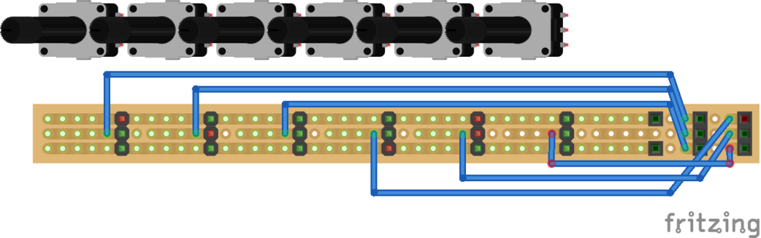
This is an extension of the previous circuit, but as the number of controls increases it becomes worth committing it to stripboard – but it is still possible to build on solderless breadboard if you prefer.
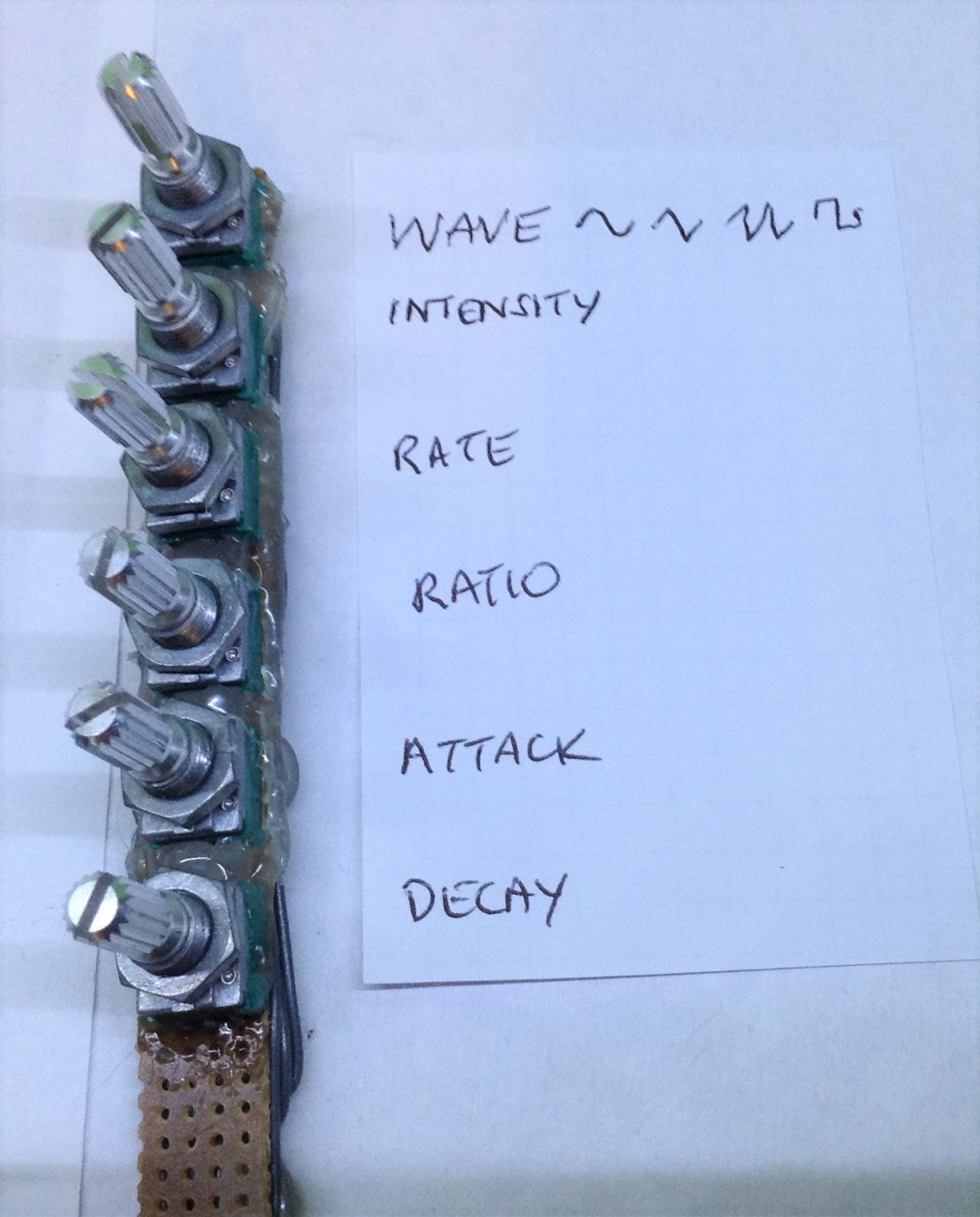
The above circuit has a 5V and GND connection to all six potentiometers and then six individual signal pins which will connect to the Arduino A0 to A5 analog inputs.
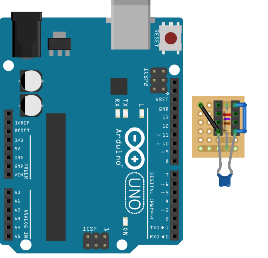
The Arduino itself will require a MIDI input on the RX pin as usual and a sound output stage on pin 9.
I’ve built up a simple Mozzi output low-pass filter, as detailed on the Mozzi site, consisting of a 270Ω resistor between pin 9 and the output jack and a 100nF capacitor between the signal and ground. I also soldered a stereo jack socket to the stripboard too, which takes the signal and sends it to the two signal pins of a stereo jack as illustrated below. Finally there are male header pins to allow the board to plug straight into the Arduino taking the signal from pin 9 and the GND from the same set of header pins.
Note that in the diagram below, the components should actually be seated on the underside of the board and I’ve represented my socket with two 4-pin female headers – but in reality it actually has four pins represented by the four ends of the two headers. If you build one yourself I expect your socket will be different to mine.
When it came to it, I ended up building it on proto board rather than stripboard and used the component legs to make the connections as can be seen below.


The Code
The code is flexible. It allows you to decide now many potentiometers to have wired into your board, allowing you to reproduce the two previous Mozzi projects if you wish.
The following potentiometers are available and can be removed by commenting out the appropriate “#define” statements at the top of the sketch.
#define WAVT_PIN 0 // Wavetable
#define INTS_PIN 1 // FM intensity
#define RATE_PIN 2 // Modulation Rate
#define MODR_PIN 3 // Modulation Ratio
#define AD_A_PIN 4 // ADSR Attack
#define AD_D_PIN 5 // ADSR Delay
These defines double as specifying the analog pins (0=A0 through to 5=A5) to use for each function too. So, by way of example, the following should mean that the code has reproduced the three-potentiometer sketch (using A0, A1 and A2) used in the Arduino FM MIDI Synthesis with Mozzi – Part 2.
//#define WAVT_PIN 0 // Wavetable
#define INTS_PIN 0 // FM intensity
#define RATE_PIN 1 // Modulation Rate
#define MODR_PIN 2 // Modulation Ratio
//#define AD_A_PIN 4 // ADSR Attack
//#define AD_D_PIN 5 // ADSR Delay
Each potentiometer is scaled appropriately using bit-shifts when read (using the mozziAnalogRead function) to choose between the following ranges, and if any aren’t being used (i.e. they have been commented out as described above) then they will have the stated default value:
- WAVT – wave table: 0 to 4: 0=Sine; 1=Triangle; 2=Saw; 3=Square. Default = 0 (Sine).
- INTS – FM intensity: 0 to 1023. Default = 100.
- RATE – rate of modulation: 0 to 1023. Default = 500.
- MODR – modulation ratio: 0 to 7. Default = 5.
- AD_A – ADSR attack time: 0 to 255. Default = 50.
- AD_D – ADSR delay time: 0 to 255. Default = 200.
In order to keep the updateControl() function running fairly quickly I only scan one potentiometer on every run of the function. Any potentiometer not being scanned will keep its previous value so it can still be used in the calculations. I only update the wavetable and envelope if the potentiometer value actually changes. The modulation frequency is updated every time.
Once again the main carrier frequency comes from the MIDI note on message, and MIDI note on and off messages trigger the different stages of the envelope.
As there are two places where I have to do something different depending on the value of a variable (when choosing the wavetable, and when deciding which potentiometer is being read) I’ve used a switch () {} statement. I don’t think this has appeared in my code up to this point, but its fairly easy to think about. A switch statement has different code for each listed value of the variable (each “case”) in the switch() statement. Once the code for that value is done, then a “break” statement indicates the end of processing.
Aside: I had a weird problem with the initial version of my code. I was finding that disabling the intensity pot and using a fixed value of 500 was yielding massively different results to using a real potentiometer that was reading 500 directly. It turns out that the problem was with the use of the AutoMap function from the original example.
AutoMap is meant for times when you don’t really know what the maximum and minimum values of your sensor reading might be – when they need calibration before use (such as if using light sensitive resistors or touch sensors or similar). When used with a pot, it works out pretty quickly the fixed range of the potentiometer, but when used with a fixed value it seems to output a much smaller range of outputs thus changing the sounds significantly.
I must admit I still don’t really understand it fully, but removing the use of AutoMap, which isn’t needed in this case anyway, seems to have sorted it out.
I think the rest of the code is pretty much as used before in Arduino FM MIDI Synthesis with Mozzi – Part 2.
Update: The code now supports a MIDI_PASS_THRU mode, which is disabled by default. For details, see Arduino Nano Multi-pot FM and String Synthesis.
Closing Thoughts
As you can hear if you watch the video there are now quite a number of sound options to explore with this project. It is still possible to go further adding more potentiometers and controllable synthesis parameters, but it will need some kind of analog multiplexing to get more inputs (or a different Arduino board such as the Nano) and it starts to become a significant hardware build pretty quickly.
Moving forward, it would be interesting to use these six potentiometers as controls for combining six oscillators in a basic additive synthesis function and see how that sounds. I also wonder if there are ways to build in custom wavetables in Mozzi – that is something I haven’t really looked at yet. There are also other types of synthesis possible – I think I saw a demo that implemented phase distortion synthesis (PD Synthesis) too.
With all this work though it is still only a monophonic sound module – it will only play one note at once. With enough processing power it is possible to run several parallel oscillators, representing different notes being played, and have them combined mathematically in the updateAudio function. I’ve seen one demo of six-note polyphony online, but it was only using fairly simple synthesis. For serious polyphonic synthesis I think it would be worth looking at the more powerful Teensy microcontroller board.
Kevin